A communication bus is a set of lines and rules that lets two digital components exchange data — typically a microcontroller and its sensors, memories or displays. This page is the entry hub to the three protocols most common on a project: UART, I2C and SPI. It places them relative to one another and gives the method for choosing, without detailing each one (that is what the child pages are for).
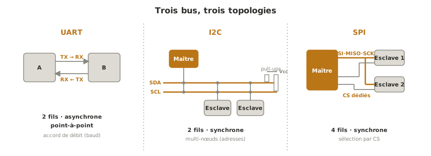
What is it for?
A microcontroller rarely works alone: it reads sensors, writes to a display, stores on a memory card, and sometimes talks to another microcontroller. Rather than a dedicated wire per piece of information, a bus standardises the way data travels over a few wires, which saves pins and makes components interchangeable.
Choosing a bus means weighing up several parameters:
- the number of wires used, and so of pins taken up on the microcontroller;
- the data rate you can reach;
- the distance over which the link stays reliable;
- the number of components you can hang on the same wires;
- the complexity of putting it to work, in wiring and in code.
This choice is made during the concept phase (when the architecture is settled) and frozen in the technical design file (at wiring and layout time).
How do you choose a bus?
Four distinctions shape the landscape. A bus is serial (the bits go one after another, over few wires, the case in embedded work) or parallel. It is synchronous when a clock line paces the exchanges, asynchronous when both sides have to agree on a data rate in advance. It is point-to-point (two components only) or multi-node (several components on the same wires). Finally, it exchanges in one direction at a time, or full-duplex (both directions at once).
The three common protocols line up like this:
| Protocol | Wires | Clock | Components | Data rate | Distance | Typical use |
|---|---|---|---|---|---|---|
| UART | 2 (TX/RX) | no (asynchronous) | 2 (point-to-point) | moderate | a few metres | debug console, GPS, serial modules |
| I2C | 2 (SDA/SCL) | yes (synchronous) | several (addresses) | moderate | on the board (< 1 m) | sensors, displays, real-time clock |
| SPI | 4 (MOSI/MISO/SCK/CS) | yes (synchronous) | several (1 CS per peripheral) | high | very short | fast display, SD card, converter |
Three reflexes for settling it. For a simple link to a single peripheral, a commissioning console or a serial module, UART is enough. To hang several sensors without multiplying wires, I2C gathers them on two lines thanks to addressing. For a fast peripheral (graphic display, SD card, converter), SPI gives you the data rate, at the price of one select wire per component added.
On any of these buses, the logic level compatibility (3.3 V / 5 V) between components still has to be checked before wiring. And to see what really travels on the wires — and decode the exchanges frame by frame — the dedicated instrument is the logic analyser.
Beyond these three protocols, the fieldbuses — RS-485 (a rugged, multi-node serial link over tens of metres) and above all CAN (the bus of the automotive and industrial worlds, everywhere in robotics) — carry the same principles over distances and reliability demands of another order.
See also
- UART — asynchronous link, 2 wires, point-to-point
- I2C — synchronous bus, 2 wires, several components by address
- SPI — fast synchronous bus, 4 wires, selection by CS
- Microcontroller — the bus links the microcontroller to its peripherals
- Logic levels — level compatibility comes up on every bus
- Logic analyser — seeing and decoding what travels on a bus