The XIAO ESP32-S3 is a stamp-sized development board (≈ 21 × 17.8 mm) from Seeed Studio, built around the ESP32-S3 chip: two cores at 240 MHz, 8 MB of PSRAM, Wi-Fi and BLE, all on a USB-C board that fits on a fingernail. This page is the board’s route hub: why this one, which variant to choose, and how to use it on a project by leaning on the pages that already exist. XIAO is a form factor, not a chip family: everything about the SoC, the radios and the toolchains is carried by the ESP32 module, and the choice between microcontroller families stays with microcontroller.
Why the XIAO ESP32-S3?
You reach for this board when you want the connectivity and the power of an ESP32 in a minimal footprint:
- stamp-sized form factor (≈ 21 × 17.8 mm, castellated edges that mount as an SMD part) — ideal for a wearable object or a compact product;
- ESP32-S3: two Xtensa LX7 cores at 240 MHz, 8 MB of PSRAM + 8 MB of Flash, vector instructions for embedded AI;
- Wi-Fi 4 (2.4 GHz) + BLE 5 built in, with a ceramic antenna and an external antenna connector;
- native USB-C: the ESP32-S3 handles USB without an external chip;
- on-board LiPo charging (battery pads on the back) and a very frugal deep sleep mode → battery operation.
The price of miniaturisation: only eleven pins come out on the edges (see below), and the board runs at 3.3 V: sensors and modules running at 5 V need a level adaptation (see logic levels).
Choosing your variant
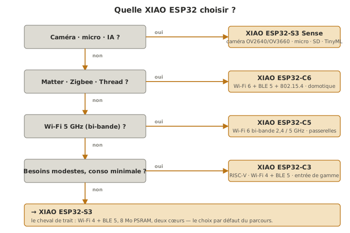
XIAO offers the same form factor on several ESP32 chips. The choice starts from the project’s need, not from the datasheet.
| Variant | Core | RAM / Flash | Radios | Signature peripheral | Choose it if… |
|---|---|---|---|---|---|
| ESP32-S3 | Xtensa LX7 ×2, 240 MHz | 8 MB PSRAM / 8 MB | Wi-Fi 4 + BLE 5 | — (reference board) | you want the Wi-Fi + BLE + power balance |
| ESP32-S3 Sense | same as S3 | 8 MB PSRAM / 8 MB | Wi-Fi 4 + BLE 5 | OV2640/OV3660 camera + microphone + microSD | vision, audio, embedded AI |
| ESP32-C3 | RISC-V, 160 MHz | 400 KB / 4 MB | Wi-Fi 4 + BLE 5 | — | modest needs, minimum consumption |
| ESP32-C6 | RISC-V (HP + LP) | 512 KB / 4 MB | Wi-Fi 6 + BLE 5 + 802.15.4 | Thread / Zigbee / Matter | interoperable home automation |
| ESP32-C5 | RISC-V | 512 KB / 4 MB | dual-band Wi-Fi 6 (2.4 / 5 GHz) | — | gateway, 5 GHz Wi-Fi |
Putting it to work on a project
Programming this board calls on the same building blocks as any microcontroller: inputs/outputs, communication, wireless, low power. The table below sends each need to the page that explains it — to get started, read it top to bottom; otherwise, go straight to what is missing. And to run a project end to end (putting numbers on the needs, choosing, designing, programming, testing), everything is laid out in building the embedded subsystem, where the XIAO comes in at the choosing the hardware step.
| Need | Go and see |
|---|---|
| programming in C++ (Arduino) | Arduino + ESP32 Arduino core |
| programming in MicroPython | MicroPython |
| the GPIO / PWM / ADC basics | GPIO · PWM · ADC |
| communicating (I²C / SPI / UART) | communication buses |
| connecting over Wi-Fi | ESP32 Wi-Fi |
| connecting over Bluetooth (BLE) | ESP32 BLE |
| reacting to an event | interrupt · timer |
| saving battery | deep sleep + ESP32 deep sleep |
| doing several things at once | FreeRTOS |
| structuring your code | firmware |
| trying it without hardware | Wokwi — the XIAO C3, S3 and C6 are simulated there |
Three pages cover what is specific to the board: the first flashing with getting started, powering and battery charging with power, and the camera/AI version with XIAO Sense.
The eleven pins
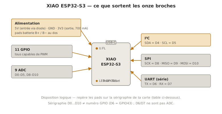
The ESP32-S3 SoC exposes some forty GPIO, but the XIAO form factor brings out only eleven of them (D0–D10), plus the power pins. This is the board’s number one constraint.
| Pad | GPIO | ADC | Touch | ”Default” role |
|---|---|---|---|---|
| D0 | GPIO1 | ✓ | ✓ | — |
| D1 | GPIO2 | ✓ | ✓ | — |
| D2 | GPIO3 | ✓ | ✓ | strapping |
| D3 | GPIO4 | ✓ | ✓ | — |
| D4 | GPIO5 | ✓ | ✓ | I²C SDA |
| D5 | GPIO6 | ✓ | ✓ | I²C SCL |
| D6 | GPIO43 | — | — | UART TX |
| D7 | GPIO44 | — | — | UART RX |
| D8 | GPIO7 | ✓ | ✓ | SPI SCK |
| D9 | GPIO8 | ✓ | ✓ | SPI MISO |
| D10 | GPIO9 | ✓ | ✓ | SPI MOSI |
On the power side: 5V (the USB output, or an input through a series diode), 3V3 (regulated output, up to 700 mA), GND, and the B+ / B− battery pads on the back. A user LED is wired to GPIO21, plus a charging LED and the Boot/Reset buttons.
Pin pitfalls
- The D0…D10 silkscreen is not the GPIO number. In Arduino you can write
D6, but elsewhere (MicroPython, many libraries) it is the GPIO number that is expected, andD6means GPIO43, not GPIO6.- Nine ADC pads only: D0–D5 and D8–D10. D6/D7 are reserved for the UART (no analogue), and on the Sense A11/A12 (GPIO41/42) do no ADC despite their name.
- No DAC on the ESP32-S3, unlike the classic ESP32: for a true analogue output, an external converter or filtered PWM (see DAC).
- Strapping pins: the Boot button is on GPIO0, and D2 (GPIO3) is a strapping pad: a level forced at start-up can prevent booting or flashing. Keep it free at reset if you can.
Extending the inputs/outputs
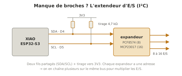
Eleven pins runs short fast. The standard answer is an I/O expander on the I²C bus: two wires (SDA on D4, SCL on D5) drive a chip such as the PCF8574 (8 I/O) or the MCP23017 (16 I/O), addressable: you can chain several on the same bus.
The other route, with no soldering, is the XIAO expansion ecosystem: the Expansion Base (OLED screen, RTC, buzzer, microSD reader, Grove connectors) and the Grove modules plug straight in and give access to the common peripherals without fine wiring.
The antenna, internal or external
The board carries a ceramic antenna, active by default, and an external antenna connector (U.FL / IPEX) with an antenna supplied. You plug in the external antenna to gain range: inside an enclosure (a metal one especially), close to a battery or a ground plane, or for a long distance.
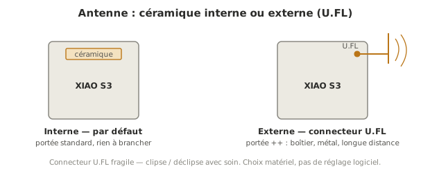
Two precautions: the U.FL connector is fragile (clip and unclip it carefully, holding the connector and not the cable), and the choice is hardware, not a software switch.
Form factor and mounting
The castellated edges let you solder the XIAO straight onto your own board, like an SMD module: this is the step from prototype to product (see PCB design). With soldered headers, the 2.54 mm pitch stays breadboard- and perfboard-compatible. Power comes in through USB-C or through the pads (5V via a diode, or a battery on B+/B−).
See also
- ESP32 — the SoC, the radios, the toolchains (the chip route)
- Microcontroller — an overview of the families and help choosing between them
- XIAO — getting started — first flashing, buttons, USB
- XIAO — power — battery charging, low power
- XIAO Sense — camera, microphone, microSD, embedded AI
- Building the embedded subsystem — the project approach from end to end
- Choosing the hardware — the step where the XIAO enters the project
- Wokwi — simulating the board and its code in the browser, before the hardware
- I²C — the bus for the I/O expander
- Deep sleep — the low-power mode for battery operation