Getting started with the XIAO ESP32-S3 means installing board support in the Arduino IDE, having the board recognised by the computer over USB-C, and uploading a first program. Since the board is an ESP32-S3, the procedure is the one in getting started with the ESP32. It is adapted here to what the form factor brings: headers to solder, an antenna to clip on, a user LED that is active low, and above all the recovery sequence for when the board “disappears”.
Before you start
The XIAO ships without headers: solder the pins you need (watch out for solder bridges, the board is tiny). For Wi-Fi/BLE, clip the supplied antenna onto the U.FL connector — one side into the block first, then press the other; never pull on the cable to remove it.
Installing support and uploading (Arduino)
- Install the Arduino IDE (stable release).
- File → Preferences → Additional boards manager URLs, add:
https://raw.githubusercontent.com/espressif/arduino-esp32/gh-pages/package_esp32_index.json - Tools → Board → Boards Manager, search for
esp32(Espressif) and install the latest version (you need 2.0.8 or later). - Select the
XIAO_ESP32S3board and the port (aCOM3or higher on Windows; ausbmodem/usbserialon macOS — if in doubt, unplug and replug to see which one disappears). - Open File → Examples → 01.Basics → Blink and upload: the orange LED starts blinking.
The full walkthrough (and the ESP-IDF alternative) is detailed in getting started with the ESP32 and ESP32 Arduino-core. Here we keep to the minimum needed to validate the board.
First program: the blinking LED
The user LED is wired to GPIO21, and it is active low: a LOW level turns it on, a HIGH level turns it off. This is the classic “Blink the wrong way round” trap.
In Arduino:
void setup() {
  pinMode(LED_BUILTIN, OUTPUT);   // LED_BUILTIN = GPIO21
}

void loop() {
  digitalWrite(LED_BUILTIN, LOW);   // on (active low)
  delay(500);
  digitalWrite(LED_BUILTIN, HIGH);  // off
  delay(500);
}
The same in MicroPython (once the MicroPython firmware has been flashed, see MicroPython):
from machine import Pin
from time import sleep

led = Pin(21, Pin.OUT)
while True:
    led.value(0)   # on
    sleep(0.5)
    led.value(1)   # off
    sleep(0.5)
To check that the radios answer, run a Wi-Fi or BLE scan next (see Wi-Fi and BLE).
Recovering a board that no longer responds
Sooner or later a bad program (or a badly set deep sleep) makes the board “disappear”: no port at all, or a port that is there but the upload fails. The way out is bootloader mode, forced with the BOOT button.
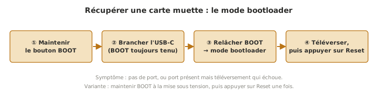
Once in bootloader mode, upload a healthy program (Blink will do), then press Reset to start it. The Reset button on its own simply restarts the program already in place.
Serial monitor blank or erroring?
The ESP32-S3 handles USB natively (there is no dedicated serial chip). If the monitor stays silent or throws an error when it opens, turn on the “USB CDC On Boot” option in the Tools menu, then upload again. For working with the serial link, see serial monitor.
Where it fits in the project
- Step 4 of the proof of concept phase. The first upload onto the target board validates the whole chain at once (IDE, ESP32 support, native USB, board and port selection). Until Blink blinks, no downstream measurement or control loop is credible.
- Every downstream XIAO and ESP32 page. The bootloader sequence and the USB CDC On Boot option unblock most of the sessions that get stuck. Learning them here, on trivial code, avoids rediscovering them under project pressure.
The stamp-sized form factor adds a constraint of its own: soldering and antenna come before the first attempt, and a badly soldered board gives the same symptoms as a software problem. Validating the bare board early in the PoC removes that doubt.
See also
- XIAO ESP32-S3 — the board’s hub (pinout, variants, use)
- Getting started with the ESP32 — the reference procedure, in detail
- ESP32 Arduino-core — the Arduino core for the ESP32
- Serial monitor — talking to the board
- MicroPython — the other way to program it
- XIAO — power — powering and charging the board