Getting started with the ESP32 means installing board support in the Arduino IDE, having the computer recognise the board, and uploading a first program. Compared with an Arduino, one extra step appears: the ESP32 is not known to the IDE by default, so you first have to install its support package (the Arduino core for ESP32). The target program is still Blink (making an LED flash), the embedded equivalent of “Hello World”.
What is it for?
Getting started validates, in one go, the whole chain between your code and the board: editor, compiler, ESP32 support, USB driver, board selection, port selection, upload. If any link is broken, Blink does not flash, and you will know it at once, on trivial code, rather than buried in a complex sketch.
Beyond the first program, the step plays two roles:
Diagnosing later on. When a more advanced sketch refuses to work, you will be able to tell a code problem from a toolchain problem, because Blink does work on that same chain.
Setting a reference point. The IDE, the Outils → Type de carte / Port (Tools → Board / Port) menu, the Upload button, the serial monitor: these are the moves repeated a thousand times over in the tutorials that follow. Anchoring them once on trivial code frees your attention for the rest.
Step by step
Five steps: install the IDE, add ESP32 support, plug in the board, load Blink, upload.
1. Install the Arduino IDE
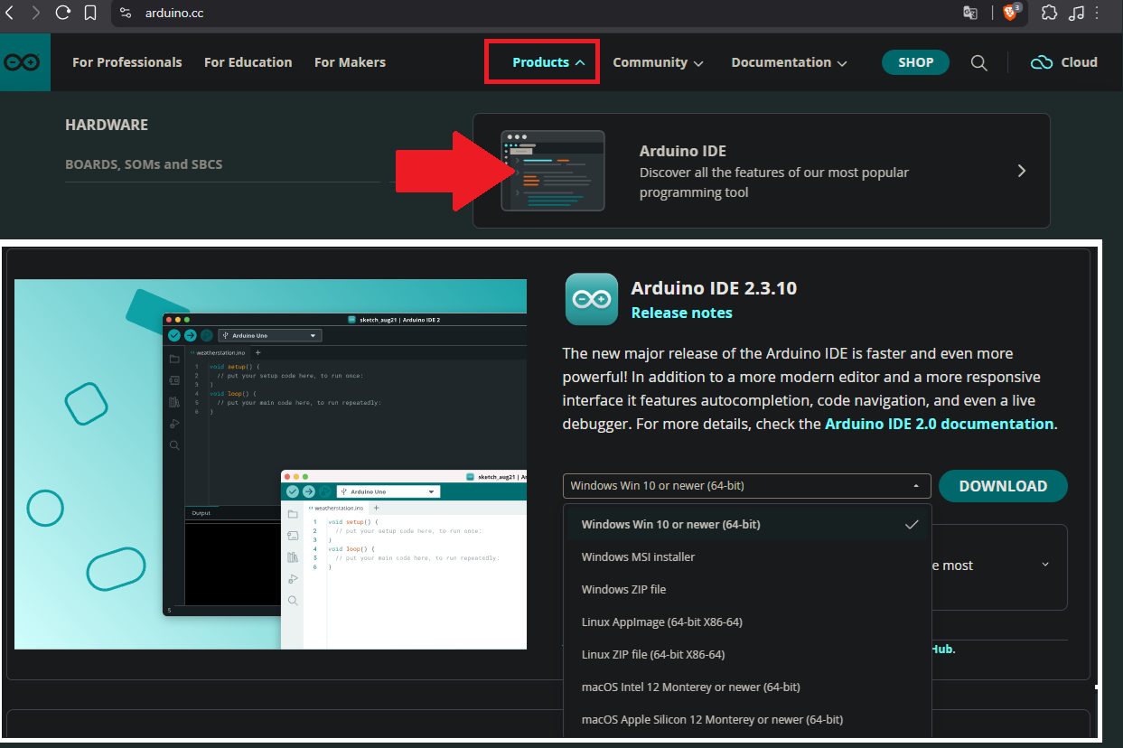
Download the IDE from the official site arduino.cc, through Products → Arduino IDE. Take the 2.x IDE (recent, recommended — autocompletion, built-in board manager). The screenshots on this page use it. The drop-down menu offers several variants per system: on Windows the ordinary installer will do, on macOS check Intel or Apple Silicon, on Linux the AppImage avoids installing anything.
On Linux, add your user to the dialout group to reach the serial port without sudo. On macOS, nothing else is needed.
2. Add ESP32 support
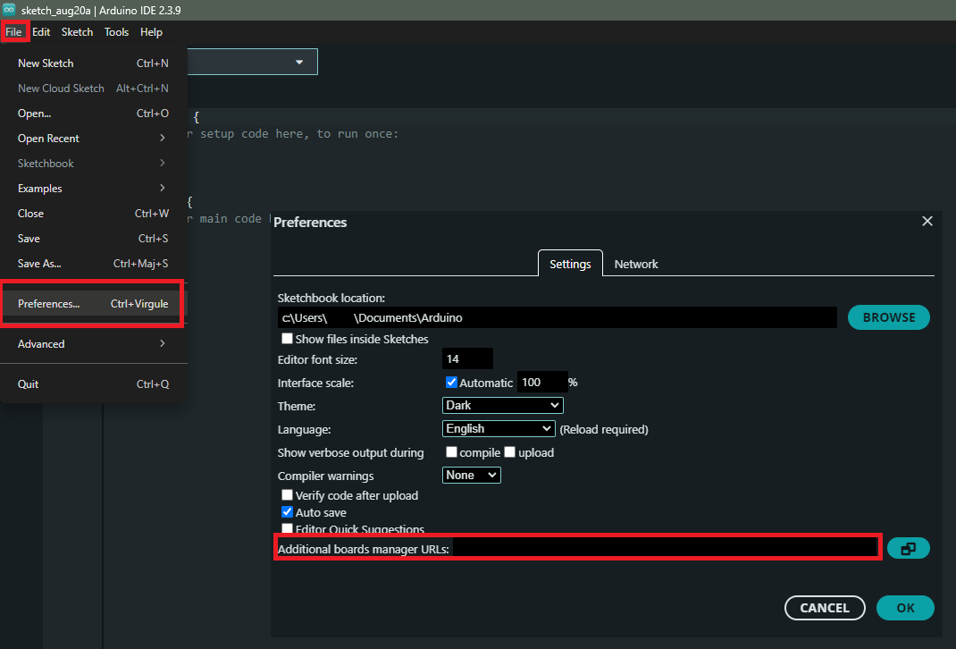
This is the step specific to the ESP32, absent from a classic Arduino start. Open Fichier → Préférences (File → Preferences) and, in the Additional boards manager URLs field, paste:
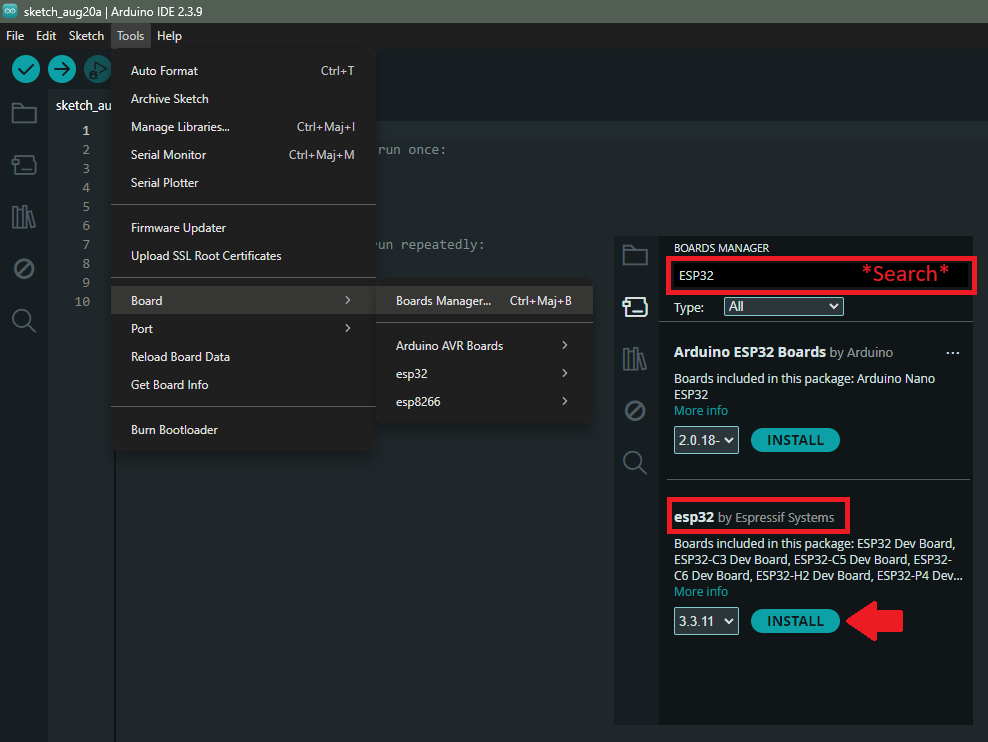
Then open the boards manager (sidebar icon, or Outils → Type de carte → Gestionnaire de cartes, Tools → Board → Boards Manager), search for esp32, and install the “esp32” package by Espressif Systems. The search returns several results: check the publisher’s name before installing.
Warning
Take version 3.0 or newer. Recent silicon (ESP32-C6, recent S3 and so on) is only recognised from core 3.0 onwards, which is built on ESP-IDF 5.1. On an earlier version the board definition does not appear and compilation fails. When in doubt, update the package before going on.
3. Plug in the board and select board plus port
Plug the board in with a USB data cable (“charge only” phone cables carry power only, with the symptom of a power LED that lights up while no port ever appears).
Most ESP32 development boards (the DevKitC type) carry a USB-to-serial interface chip:
CP2102 (Silicon Labs) — the most common one. On older Windows, install the CP210x VCP driver from the Silicon Labs site if the port does not appear.
CH340 — on some clones, with the CH341SER driver from wch-ic.com.
Native USB Serial/JTAG — on recent chips (C3, S3, C6 and so on), the board shows up directly as a USB port, with no bridge chip and no driver to install.
Two routes lead to the selection, depending on whether the IDE recognises your board or not.
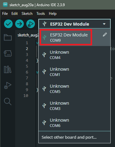
Common case — the toolbar selector. Open the selector at the top of the window: the detected boards appear there with their port. Choose yours.
On a DevKit with a CH340 bridge, the board shows as Unknown as long as it has never been paired. That is normal (see Pitfalls). Go through Select other board and port…, pick ESP32 Dev Module on the left and your port on the right: the pairing is remembered.
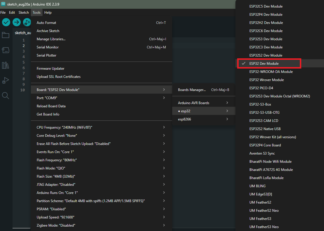
Manual route — the Outils (Tools) menus. It works in every case, including when the IDE recognises nothing. Outils → Type de carte → esp32, then your model: “ESP32 Dev Module” suits most generic DevKits (otherwise the exact model: ESP32-C3 Dev Module, ESP32-S3 Dev Module and so on).
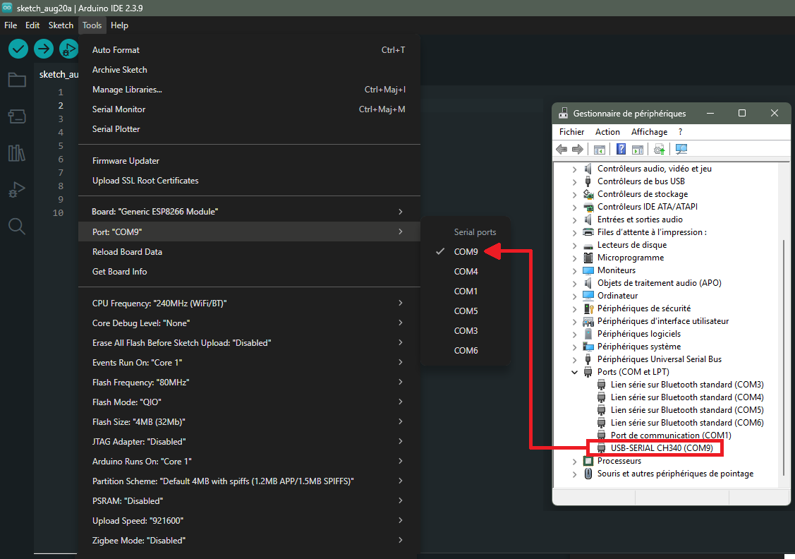
Then Outils → Port: COMx on Windows, /dev/cu.usbserial-... or /dev/cu.usbmodem... on macOS, /dev/ttyUSB0 or /dev/ttyACM0 on Linux.
What remains is to work out which of those ports is yours. On Windows, the device manager names it explicitly: under Ports (COM et LPT), the board appears under the name of its interface chip, here USB-SERIAL CH340 (COM9). The other entries in the list are most often Bluetooth serial links, unrelated to the board: they are what fills the port selector with “Unknown”.
4. Load Blink
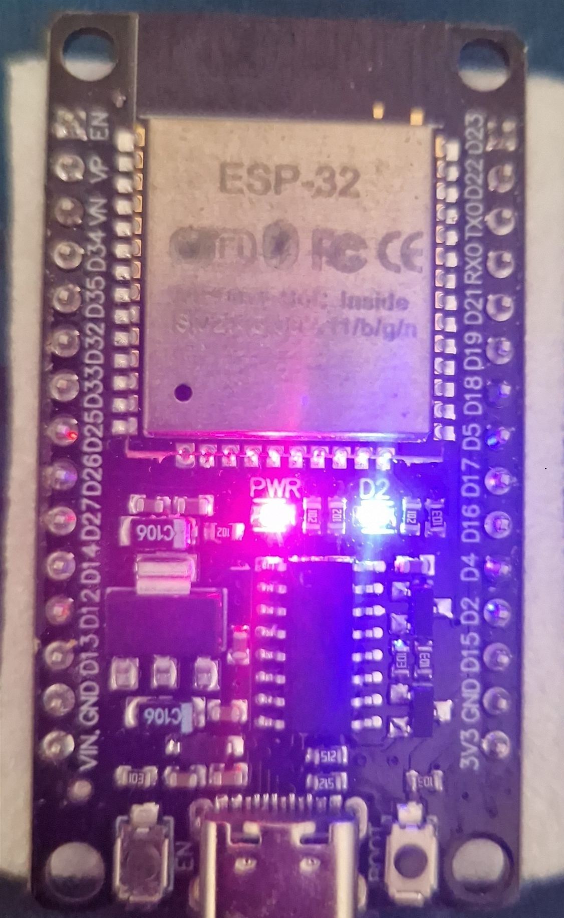
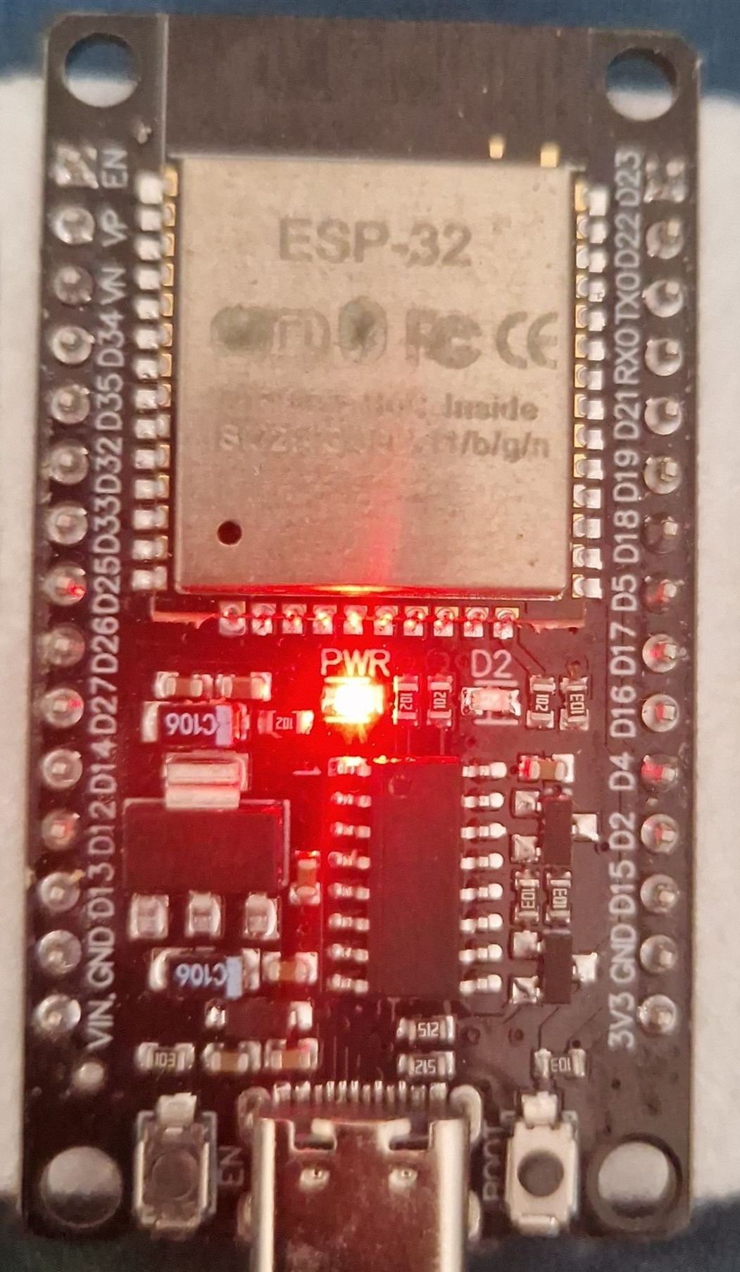
Type in (or paste) this sketch. The built-in LED of most DevKits is wired to GPIO 2, the pin silkscreened D2 on the board:
Two functions give every program its structure: setup() runs once at start-up, loop() then repeats indefinitely. The program declares the pin as an output, then lights it for a second, switches it off for a second, and starts again.
Warning
Do not use LED_BUILTIN on the ESP32. The Blink example shipped with the IDE uses that constant, inherited from the Arduino Uno where the LED sits on pin 13. Many ESP32 board definitions do not define it, and compilation stops on 'LED_BUILTIN' was not declared in this scope. Writing the GPIO number works everywhere.
Click Vérifier (Verify, the tick icon): this is compilation. If everything is correct, the console prints the size of the binary, with no red line.
5. Upload and watch
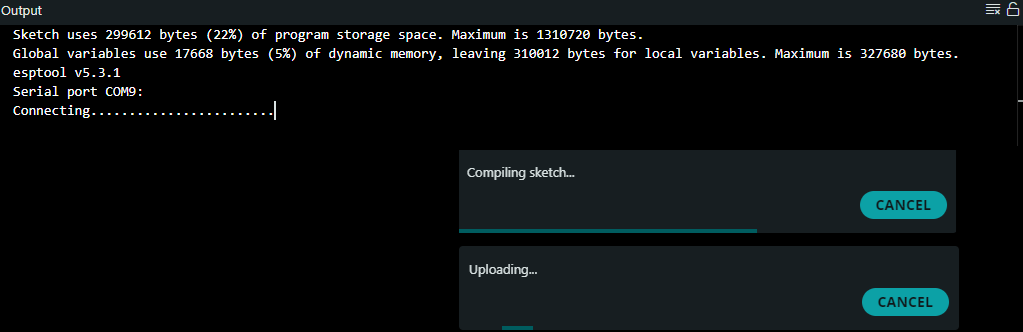
Click Téléverser (Upload, the arrow icon). The IDE recompiles and sends the binary over the port. The console first summarises the space taken in flash and in RAM, then shows Connecting...... while esptool tries to get the board into download mode.
Tip
If the upload does not enter programming mode. Many ESP32 boards (especially CH340 bridge clones) lack the auto-reset circuit that switches them into download mode on their own. Hold the BOOT button (sometimes labelled IO0) down for the whole upload, from the click on Téléverser until the writing ends. The flashing tool performs its own reset after the click: a press released before that reset, or made before clicking, has no effect.
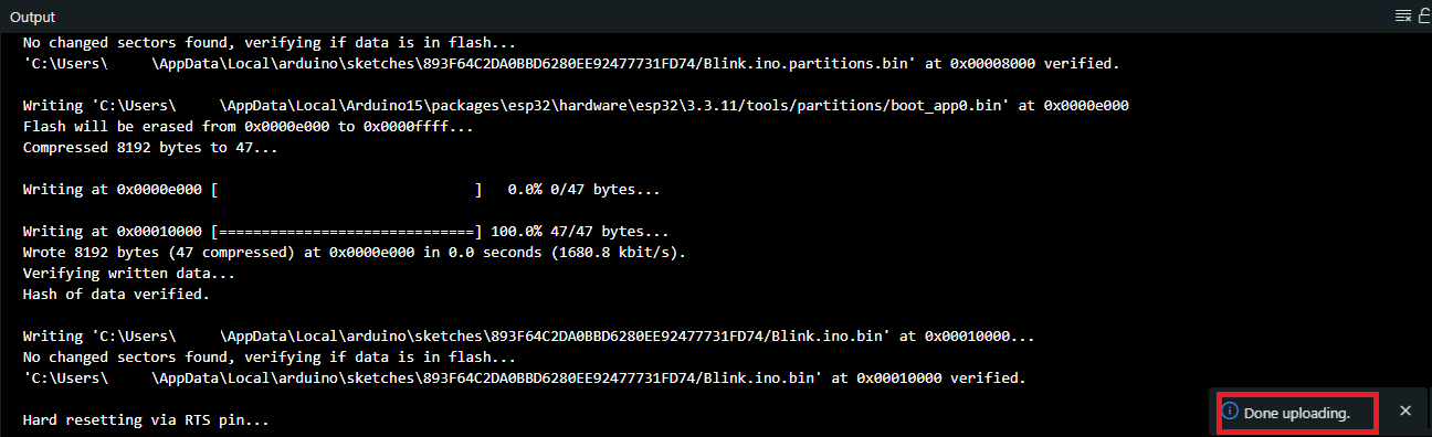
Once it is done, the console verifies what it wrote (Hash of data verified.), restarts the board (Hard resetting via RTS pin...) and announces Done uploading.
The LED then flashes at a one-second rhythm. The program is running: getting started is validated.
Example — A modified Blink
To check that you really control what happens (and not just that you managed to upload some code), change the delays:
Upload again: the LED now gives a short flash (100 ms) every second. This small step — edit, upload, observe the expected change — is the basic move behind every tutorial that follows.
Pitfalls
ESP32 support not installed. Without step 2, no ESP32 board appears in Outils → Type de carte, and pasting ESP32 code into the IDE is not enough. It is the most frequent omission when coming from Arduino, where the AVR boards are recognised out of the box.
The wrong package installed. Searching for esp32 also brings up “Arduino ESP32 Boards” by Arduino, placed higher in the list. That one only adds the Arduino Nano ESP32: on a generic DevKit, no usable definition appears afterwards in Outils → Type de carte, and you end up suspecting the cable or the driver long before the package. Check the publisher: Espressif Systems.
A core too old for the chip. A recent board (C6, for example) compiled on a core earlier than 3.0 does not offer its definition, or fails to compile. Update the package.
Upload stuck for want of programming mode.Connecting....____ that never completes: the board has not entered the bootloader. Hold BOOT for the whole upload (see the tip above).
Wrong boot mode detected (0x13). This message does not announce a dead board, quite the opposite: to emit it, the tool has talked to the chip, so the cable, the port and the board all work. It only reports that the ESP32 started in normal execution instead of download mode, because GPIO0 (BOOT) was not held low at the moment of the reset. Hold BOOT for the whole upload.
A port marked Unknown. On a CH340 bridge board, the IDE shows Unknown next to the port: the bridge announces its own USB identifier, not that of a board, so the IDE has nothing to attach the port to. This is not a driver fault: Windows, for its part, does show the chip. Pair the board with the port once through Select other board and port…: the pairing is remembered.
Missing USB-to-serial driver (Windows). Board powered but no port at all: the CP210x (CP2102) or CH340 driver has to be installed. Chips with native USB (C3/S3/C6) do not have this problem.
'LED_BUILTIN' was not declared in this scope. The Blink example shipped with the IDE uses that constant, inherited from the Arduino Uno where the LED sits on pin 13. Many ESP32 board definitions do not define it: compilation stops dead. Replace it with the real GPIO number, 2 on most DevKits, silkscreened D2. On boards where it is defined, redefining it yourself raises a redefinition warning: better to use a constant of your own.
An addressable RGB built-in LED (C3, S3, C6 and so on). On many recent DevKits, the soldered LED is not a plain LED but an addressable WS2812: it is driven by a data frame, not by a logic level. A digitalWrite Blink therefore cannot light anything, whatever pin is given: changing the GPIO number will not fix it. For these boards, core 3.x exposes the constant RGB_BUILTIN and the function neopixelWrite(RGB_BUILTIN, red, green, blue), illustrated by the official BlinkRGB example. Check what kind of LED your board has before concluding that it is dead.
Power dropout (brown-out) on a weak USB port. The ESP32 draws current spikes. On a weak USB port or a poor cable, the voltage sags and the board reboots in a loop (Brownout detector was triggered). Change USB port or cable, and avoid unpowered hubs.
Exercises
Exercise 1 — Two rhythms
Modify Blink so that the LED stays lit for 2 seconds, then flashes quickly three times (100 ms on / 100 ms off), before starting over.
Answer to exercise 1
const int LED = 2;void setup() { pinMode(LED, OUTPUT);}void loop() { digitalWrite(LED, HIGH); delay(2000); digitalWrite(LED, LOW); delay(300); for (int i = 0; i < 3; i++) { digitalWrite(LED, HIGH); delay(100); digitalWrite(LED, LOW); delay(100); }}
The for loop factors out the three flashes. You will meet this need for “rhythms” without a blocking delay again in non-blocking programming: the pattern is covered there on the Arduino side, and it transposes as it stands to the ESP32.
Exercise 2 — An external LED
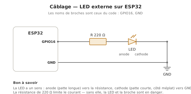
Wire an external LED (with its series resistor of about 220 Ω) to GPIO 16 and make it flash, without touching the built-in LED. Which line changes?
Answer to exercise 2
Only one thing changes: the pin being driven.
const int LED = 16;void setup() { pinMode(LED, OUTPUT);}void loop() { digitalWrite(LED, HIGH); delay(500); digitalWrite(LED, LOW); delay(500);}
The pin is declared as a const int (a typed constant) rather than as a #define (see configuring the GPIO for the choice of safe pins). Anode of the LED to GPIO 16 through the resistor, cathode to GND.
Special case — Arduino core, ESP-IDF, PlatformIO
This page uses the Arduino core for ESP32: the same API as the Arduino (setup(), loop(), digitalWrite and so on), which is the recommended route to begin with (covered in detail in the ESP32 Arduino core). For finer native control (fine-grained multitasking, low-level network stack), Espressif provides ESP-IDF, its native environment (see discovering ESP-IDF). PlatformIO (a VS Code extension) handles both, and makes Git versioning and multi-file projects easier.
Where it fits in the project
Step 4 of the proof of concept phase — the first compilation and the first upload onto the target board are the founding act of the software proof of concept. As long as Blink does not flash, no downstream measurement or control loop is credible.
Every downstream ESP32 tutorial — without having actually got started, reading the other tutorials with no way to test comes down to reading code without running it. Do Blink at least once, on the target hardware, as early as possible.
Investing half an hour to validate the complete chain at the beginning of the proof of concept saves hours of hybrid bugs later, when a toolchain problem can no longer be told apart from an algorithm problem.