Configuring the GPIO (General Purpose Input/Output) pins of an ESP32 means choosing which pins to read or drive, and how. It is the basic move behind every interaction with the physical world — reading a button, lighting an LED, measuring a voltage, driving an actuator. The ESP32 offers plenty of pins, but they are not all equivalent: some are reserved, others carry constraints at start-up. Knowing which ones to use avoids most of the circuits that “do not work for no reason”. The general concept of an input/output pin is covered in GPIO. This page gives its ESP32 incarnation.
What is it for?
On the ESP32, choosing and configuring pins properly determines three things:
That the circuit works at all. Wiring a button to a pin reserved for the Flash memory, or expecting an internal pull-up on a pin that has none, produces erratic behaviour that no amount of software debugging will fix.
That the board boots. A few pins (strapping pins) are read at reset to select the boot mode. A circuit that forces them can prevent start-up.
That the measurement is readable. Analog inputs have constraints of their own (range, conflict with Wi-Fi) that must be known before trusting a reading.
The pins of the ESP32
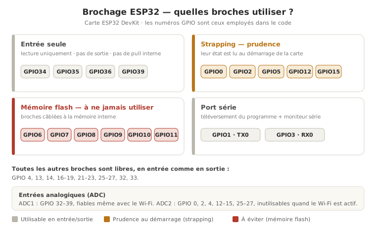
The original ESP32 exposes numbered GPIO (GPIO0 to GPIO39, with gaps: 20, 24 and 28 to 31 are not brought out of the package). They are referred to by number, not by a position on the board. A few categories worth knowing:
General-purpose pins — most of them: input, output, internal pull, PWM. Prefer these.
Input-only pins — GPIO34, 35, 36, 39: reading only, no output, no internal pull resistor. Perfect for an analog sensor, to be avoided for driving anything, or for a button without an external pull.
Flash pins — GPIO6 to GPIO11: used by the board’s Flash memory. Do not touch them, or the chip will crash.
Serial pins — GPIO1 (TX) and GPIO3 (RX): this is UART0, the one used by the serial monitor. Leave them free as long as it is in use.
Strapping pins — GPIO0, 2, 5, 12, 15: read at reset to select the boot mode. Usable, but with care (see Pitfalls).
Warning
The ESP32 runs at 3.3 V and is not 5 V tolerant. Applying 5 V to an input can destroy the pin. Any 5 V signal (sensor, module) goes through level shifting (see voltage levels). This is the most treacherous difference from the Arduino.
Configuring a digital pin
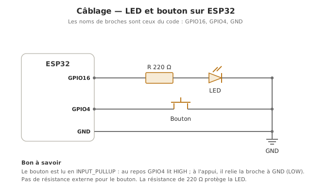
As everywhere, two steps: declare the direction in setup(), then read or write in loop().
const int LED = 16; // outputconst int BOUTON = 4; // inputvoid setup() { pinMode(LED, OUTPUT); pinMode(BOUTON, INPUT_PULLUP); // internal pull-up enabled}void loop() { bool appuye = (digitalRead(BOUTON) == LOW); // PULLUP: LOW when pressed digitalWrite(LED, appuye ? HIGH : LOW);}
pinMode accepts INPUT, OUTPUT, INPUT_PULLUP and, an ESP32 specific feature absent from the Arduino AVR, INPUT_PULLDOWN (internal pull towards ground). The internal pull avoids a floating input: a bare INPUT pin picks up ambient noise and reads anything. Reminder: pins GPIO34-39 have no internal pull at all. A button on one of them requires an external resistor.
Tip
Constants in const, not in #define. Declaring const int LED = 16; is typed and readable. The compiler checks how it is used. Keep #define for what const cannot do (conditional compilation, macros).
Reading an analog input
analogRead(pin) returns the voltage on the pin over a 12-bit scale: 0 to 4095 (and not 10 bits / 0-1023 as on the Arduino Uno). The principle of analog-to-digital conversion is covered separately (see ADC). Two major ESP32 constraints:
A naive conversion lies at the top of the range. Attenuation is already 11 dB by default: the full 0-3.3 V range is covered without setting anything. The ADC response, however, is not linear near the top of the scale, and a brut * 3.3 / 4095 calculation inherits that. For an accurate voltage, use analogReadMilliVolts(pin), which relies on the calibration data burned into the chip. (analogSetAttenuation() is there to reduce the range and gain resolution on a low-voltage sensor, not to extend it.)
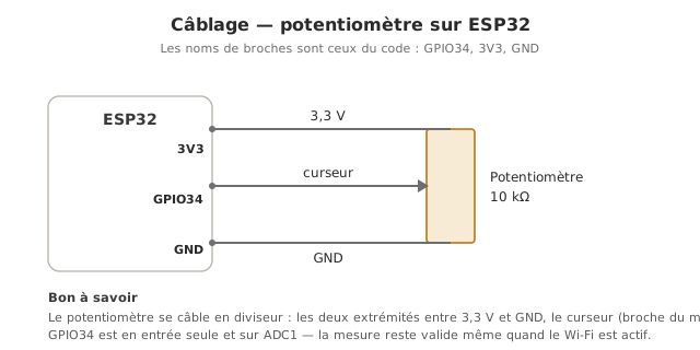
ADC2 / Wi-Fi conflict. The pins of the ADC2 converter (GPIO0, 2, 4, 12-15, 25-27) are unusable as soon as Wi-Fi is active. For an analog measurement in a connected project, use ADC1: GPIO32 to GPIO39.
const int POTAR = 34; // ADC1, Wi-Fi compatible, input onlyvoid setup() { Serial.begin(115200);}void loop() { int brut = analogRead(POTAR); // 0..4095, raw value int mV = analogReadMilliVolts(POTAR); // calibrated voltage, in millivolts Serial.print(brut); Serial.print(" -> "); Serial.print(mV / 1000.0, 2); // the same, in volts Serial.println(" V"); delay(200);}
Driving with PWM (brightness, speed)
The ESP32 has no historical analogWrite: pulse-width modulation goes through the LEDC peripheral. With core 3.x, you attach a pin to a frequency and a resolution, then write a duty cycle:
Wiring: this is the same LED on GPIO16 as in the digital section (see its diagram above).
Warning
The LEDC API changed in core 3.0. The code above (ledcAttach(pin, freq, bits) + ledcWrite(pin, duty)) assumes a core ≥ 3.0. On a 2.x core, the API was ledcSetup(channel, freq, bits) + ledcAttachPin(pin, channel) + ledcWrite(channel, duty). If ledcAttach cannot be found, it is a version question (see getting started, step 2).
The concept of PWM itself (duty cycle, frequency) is covered separately (see PWM).
Pitfalls
An input-only pin used as an output.GPIO34-39 cannot drive an LED nor provide an internal pull. Symptom: pinMode(34, OUTPUT) has no effect, or a button that reads anything. Keep them for sensors, in reading only.
Floating input. A button on an INPUT pin with no pull (internal or external) reads HIGH/LOW at random. Use INPUT_PULLUP (or INPUT_PULLDOWN), and on GPIO34-39 an external resistor is mandatory.
ADC2 + Wi-Fi. An analog measurement that goes to zero or freezes as soon as Wi-Fi is switched on: the pin is on ADC2. Move the sensor to ADC1 (GPIO32-39).
A strapping pin constrained at boot. A circuit that forces GPIO0, 2, 5, 12 or 15 to a level at reset can prevent start-up (GPIO0 LOW = bootloader mode, GPIO12 HIGH = wrong Flash voltage). Avoid wiring them to a permanent pull, or pick other pins.
Touching Flash pins 6-11. Wiring them crashes the chip. Never use them as GPIO.
Trusting the Arduino scale.analogRead returns 0-4095 (12 bits), not 0-1023. A conversion formula copied from Uno code gives values that are wrong by a factor of 4.
Exercises
Exercise 1 — Button debouncing, one action per press
A button on GPIO4 (in INPUT_PULLUP) must toggle an LED (GPIO16) on every press: one press equals one change of state, not a blink for as long as the button is held. What is the right pattern?
Answer to exercise 1
The canonical pattern is edge detection: you store the stable state and act only on the transition. No artificial time lock.
const int BOUTON = 4;const int LED = 16;bool etatStable = HIGH; // PULLUP: released = HIGHbool etatLed = LOW;void setup() { pinMode(BOUTON, INPUT_PULLUP); pinMode(LED, OUTPUT);}void loop() { bool lecture = digitalRead(BOUTON); if (lecture != etatStable) { delay(20); // short debounce etatStable = lecture; if (etatStable == LOW) { // press edge detected etatLed = !etatLed; digitalWrite(LED, etatLed); } }}
You act on the transition to LOW (the press), not continuously. It is the same logic as for any reliable on/off input.
Exercise 2 — A dimmer driven by a potentiometer
A potentiometer on GPIO34 (ADC1) must set the brightness of an LED on GPIO16 using PWM. Map the 0-4095 reading onto the 0-255 duty cycle.
Answer to exercise 2
const int POTAR = 34; // ADC1const int LED = 16;void setup() { ledcAttach(LED, 5000, 8); // 8 bits -> duty 0..255}void loop() { int brut = analogRead(POTAR); // 0..4095 int duty = map(brut, 0, 4095, 0, 255); // rescaling ledcWrite(LED, duty); delay(20);}
map() converts the input scale (12 bits) to the PWM scale (8 bits). Turning the potentiometer varies the brightness continuously.
Where it fits in the project
Step 4 of the proof of concept phase — as soon as the first sensor or actuator is wired to the target board, the choice of pins (input only, ADC1 vs ADC2, strapping) determines how reliable the prototype will be. Wiring chosen carelessly is paid for in intermittent bugs.
Step 2 of the integration and testing phase — validating an isolated electronic part means reading its inputs and outputs, hence GPIO configured correctly and voltage levels respected.
Settling once and for all on a map of your safe pins (ADC1 for sensors, general-purpose pins for actuators, strapping pins avoided) saves rediscovering the constraints on every new circuit.
Going further
GPIO — the general concept of a digital input/output (cross-cutting).
PWM — pulse-width modulation in detail (cross-cutting).