UART is the point-to-point asynchronous serial link that lets the ESP32 talk to another device — GPS module, RFID reader, second board — over two wires (TX and RX) plus a common ground. Do not confuse it with the serial monitor: that one takes UART0 to talk to the PC over USB, whereas here a second hardware port talks to a component. The ESP32 has three of them (UART0, UART1, UART2) and, unlike the Arduino, its pins are remappable: no need to fall back on SoftwareSerial.
What is it for?
Many modules only speak serial. The hardware UART of the ESP32 handles them without taking over the monitor:
Receiving a stream. A GPS module spits out NMEA sentences continuously. You read them on a dedicated port while the monitor stays free for debugging.
Driving a module. An RFID reader, a modem or a serial display receive their commands on TX and answer on RX.
Linking two boards. Two ESP32s (or an ESP32 and an Arduino) exchange data over a direct serial link, once the voltage levels are adapted.
How the protocol works (frame, start bit, baud rate) is covered in the cross-cutting concept page UART. This page shows how to wire it and code it on the ESP32.
Step by step
Four moves: pick a free port, initialise it, wire it, exchange.
1. Pick a free port
Serial (UART0) is reserved for the monitor and the boot log: you do not use it for a module, otherwise the two streams get mixed up. So you take Serial2 (or Serial1). By default, Serial2 is wired to GPIO16 (RX2) and GPIO17 (TX2).
2. Initialise the link
Serial2.begin() takes the baud rate, the frame format, then the RX then TX pins:
const int RX2 = 16; // the ESP32 receives hereconst int TX2 = 17; // the ESP32 transmits hereSerial2.begin(9600, SERIAL_8N1, RX2, TX2);
The baud rate (9600, 115200…) must be identical on both sides. It is imposed by the datasheet of the module. SERIAL_8N1 is the most common format (8 data bits, no parity, 1 stop bit).
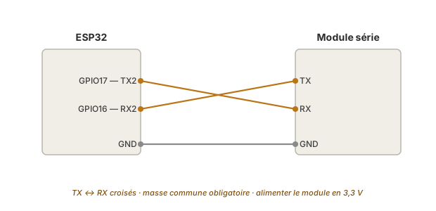
3. Wire it: TX to RX, crossed over
The golden rule of the UART: what one board transmits (TX), the other receives (RX). The two wires cross over, and the grounds must be tied together.
Warning
The pins of the ESP32 run at 3.3 V. A module transmitting at 5 V into the RX line of the ESP32 can destroy the pin. Check the output voltage of the module. Above 3.3 V, insert a level shifter (see logic levels).
4. Exchange
The functions are those of the monitor, applied to Serial2:
Serial2.available() — the number of received bytes waiting.
Serial2.read() — reads one byte.
Serial2.write() / Serial2.print() — transmits.
Example — A bridge between the module and the monitor
A concrete case: you relay in both directions what passes on Serial2 (the module) and on Serial (the monitor, so the PC). You see in the monitor what the module sends, and you can answer it by typing on the keyboard: ideal for probing an unknown serial module.
const int RX2 = 16; // receives from the module (tied to the module TX)const int TX2 = 17; // transmits to the module (tied to the module RX)void setup() { Serial.begin(115200); // UART0: to the PC Serial2.begin(9600, SERIAL_8N1, RX2, TX2); // UART2: to the module Serial.println("Serial bridge: monitor <-> module (UART2)");}void loop() { // module -> PC: every byte received on UART2 goes back to the monitor while (Serial2.available() > 0) { Serial.write(Serial2.read()); } // PC -> module: everything typed in the monitor leaves on UART2 while (Serial.available() > 0) { Serial2.write(Serial.read()); }}
Each whiledrains the queue on one side before moving to the other, without ever blocking: the loop stays responsive both ways. Open the monitor at 115200 (the baud rate of the PC, independent of the 9600 of the module): the module frames scroll past, and the text typed on the keyboard reaches it.
With the monitor open at 115200, and a module that answers AT commands:
Serial bridge: monitor <-> module (UART2)
AT
OK
+DATA:23.4,48
+DATA:23.5,48
+DATA:23.5,47
Only the first line comes from the sketch. The following ones are relayed as they are: AT left the keyboard for the module, all the rest is what the module answered. A silent module produces nothing after the first line: that is the symptom to recognise.
Pitfalls
TX wired to TX. Pitfall number one: nothing flows. TX transmits, RX listens: the two wires cross over (TX on one side to RX on the other).
Ground not tied. Without a common ground, the logic levels have no reference: erratic reception, or none at all. Always tie the GNDs together.
A 5 V signal on an ESP32 pin. A 5 V module (some GPS units, Arduino boards) burns the RX pin of the 3.3 V ESP32. Shift the level.
Using Serial for the module. Wiring a module to UART0 mixes its stream with the monitor and disturbs uploading. Keep UART0 for the PC, take Serial1/Serial2 for the modules.
GPIO16/17 on a WROVER board. On WROVER modules (8 MB of PSRAM), GPIO16 and GPIO17 are taken by the PSRAM and unavailable: remap Serial2 onto other pins (Serial2.begin(9600, SERIAL_8N1, 25, 26)). WROOM boards do not have this constraint.
Mismatched baud rates.Serial2.begin(9600…) facing a module at 115200 gives gibberish. The baud rate comes from the datasheet of the module, not from a guess.
Exercises
Exercise 1 — Counting the lines received
A module sends text line by line on Serial2. Count the lines received and print the total to the monitor on every new line. Hint: read a whole line, not a byte.
Answer to exercise 1
You read the whole line with readStringUntil('\n'), increment a counter, and send it back to the monitor.
const int RX2 = 16;const int TX2 = 17;unsigned long lignes = 0;void setup() { Serial.begin(115200); Serial2.begin(9600, SERIAL_8N1, RX2, TX2);}void loop() { if (Serial2.available() > 0) { String ligne = Serial2.readStringUntil('\n'); // up to the line break ligne.trim(); // strips spaces and \r if (ligne.length() > 0) { lignes++; Serial.print("Line "); Serial.print(lignes); Serial.print(": "); Serial.println(ligne); } }}
readStringUntil('\n') gathers the bytes up to the line break, handier than read() byte by byte for structured text.
Exercise 2 — Two modules at the same time
Make the ESP32 talk to two serial modules at once (a GPS and a display, say), each on its own UART, without touching the monitor. Which pins do you pick?
Answer to exercise 2
You keep UART0 for the monitor, and use Serial1 and Serial2 on distinct free pins.
The three hardware UARTs of the ESP32 work in parallel. Serial1must be remapped (its default pins serve the Flash). You pick two free GPIOs.
Special case — UART1 and long links
UART1 is available but its default pins are wired to the internal Flash: you must always give it free pins (Serial1.begin(baud, SERIAL_8N1, rx, tx)).
On the variants with native USB (C3, S3, C6…), Serial may be the USB Serial/JTAG, and the number of hardware UARTs available differs. Refer to the pinout of the board through configuring the GPIO.
For a long or noisy link (several metres, motors nearby), the plain UART no longer holds: you move to a differential layer such as RS-485, whose principle is sketched in communication buses.
Where it fits in the project
Proof of concept — as soon as a serial module enters the project (GPS, rangefinder, modem), the dedicated port makes it talk without disturbing debugging.
Integration and testing — linking two subsystems over a serial line is a classic of assembly. The bridge of the example serves to check each direction on its own.