Between the moment the Arduino is powered and the moment setup() runs its first useful instruction, a few tens to a few hundred milliseconds go by during which the state of the GPIO pins is not the one you coded. The concrete consequence: a relay can pull in briefly, a motor can jerk, an LED can flash at start-up. This page covers the causes, the symptoms and the fixes for that behaviour specific to boot, a subject often ignored until the day it causes trouble.
What is it for?
Three cases where you need to understand the GPIO state at boot:
- An actuator that switches on at start-up — the relay that clacks, the motor that jerks, the servo that slams to its stop at every power-up.
- A board pinout with sensitive pins — on the ESP32 in particular, some pins have to be at a precise level during boot, or the board will not start at all.
- Defined behaviour coming out of a shutdown and restart — for a system that has to come back to a safe state after a mains cut.
Step by step
Four steps: understand what happens at boot, identify the problem pins, add external pull-up or pull-down resistors, sequence the actuators at the top of setup().
1. Understand the start-up sequence
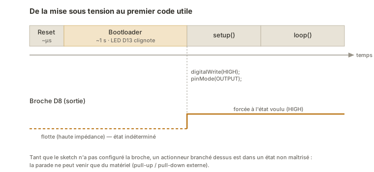
On the Arduino Uno R3 (ATmega328P), the typical chain after power-up:
- Hardware reset (~a few µs) — every pin as a floating
INPUT(high impedance). - Bootloader (~1 s, only on an external reset) — it waits for a possible update over USB and flashes LED 13. During that time, most pins stay as floating
INPUT. - Sketch starts —
setup()runs. Pins are configured aspinMode()gets called for each. loop()— normal behaviour.
During phases 1 and 2, every pin later used as an OUTPUT floats. An actuator wired to it is in an undefined state.
On the ESP32, start-up is different: some pins (called strapping pins) are read by the ROM bootloader to choose the boot mode, and their level at start-up influences the start-up itself. Those constraints belong to the chip (see ESP32 GPIO).
2. Identify the board’s problem pins
| Board | Pins sensitive at boot | Behaviour |
|---|---|---|
| Uno R3 | D13 | flashes during the bootloader (built-in LED) |
| Uno R3 | D0, D1 | used by the UART/USB — keep them clear for anything else |
| Uno R4 | D13 | flashes in DFU mode (double press on RESET), not at every power-up |
On the Uno R3, the main nuisance is the LED 13 flashing during the bootloader sequence: if an actuator (relay, motor) is wired to D13, it goes through that jitter. Simple fix: use another pin for the actuator.
The Uno R4 (Renesas RA4M1) does not use the same bootloader: it starts the sketch straight away at power-up. Its LED only flashes in DFU mode, triggered by a double press on the RESET button, not at every power-up as on the R3.
On the ESP32, it is the strapping pins (GPIO 0, 2, 12, 15) that are sensitive at boot, with constraints belonging to the chip (up to refusing to start if they are badly wired). See ESP32 GPIO.
3. Add external pull-up or pull-down resistors as needed
A floating INPUT pin can be steadied by an external resistor:
- External pull-down (a 10 kΩ resistor between the pin and GND) — the pin sits at
LOWat boot. Suits an actuator downstream that must be off until the code takes control. - External pull-up (a 10 kΩ resistor between the pin and
+5 V) — the pin sits atHIGHat boot. Suits an actuator that must be active at rest (inverted logic, or the special case of a module with an active-low input).
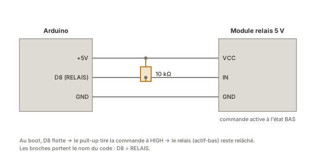
For standard relay modules (5 V, opto-isolated, active low): a 10 kΩ external pull-up between the command pin and +5 V keeps the relay released during boot, even while the pin floats. That is the generic answer to the “relay click at start-up”.
4. Sequence the actuators at the top of setup()
The first reflex to code in setup(): force every output into a safe state BEFORE configuring the OUTPUT mode. The order of the two lines matters:
void setup() {
  // CORRECT ORDER: force the state you want FIRST, then configure as OUTPUT
  digitalWrite(RELAIS, HIGH);   // for an active-low module, HIGH = released
  pinMode(RELAIS, OUTPUT);

  digitalWrite(MOTEUR_EN, LOW); // motor stopped
  pinMode(MOTEUR_EN, OUTPUT);

  // ... the rest of the initialisation
}
Why that order? When you call pinMode(X, OUTPUT), the pin switches to output mode with a default value (typically LOW). If you write digitalWrite(X, HIGH) before pinMode(X, OUTPUT), you set the internal PORT register to HIGH: so from the instant of the pinMode, the output goes straight to HIGH without passing through LOW.
Example — A relay module that clacks at start-up
Symptom: a home-automation project with a 5 V relay module driving a lamp. At every start-up of the Arduino you hear a click and then the lamp goes out. That is bad for the mechanical life of the relay and for how the system is perceived.
Diagnosis: during the bootloader, the command pin floats. The relay module (active low) reads that blur as a LOW (enough noise to cross the threshold) and pulls the relay in. Then the sketch starts and configures the pin properly as an OUTPUT at HIGH: the relay releases.
Fix:
- A 10 kΩ external pull-up between the command pin and
+5 V→ the pin is pulled toHIGHduring boot and the relay stays released (wiring in the diagram of step 3). - Code:
const int RELAIS = 8;

void setup() {
  // Force HIGH before configuring as an output
  digitalWrite(RELAIS, HIGH);
  pinMode(RELAIS, OUTPUT);
}

void loop() {
  // The relay only pulls in when explicitly asked
}
With those two measures (hardware plus software), the start-up is silent and clean.
Pitfalls
Believing pinMode(OUTPUT) initialises to LOW. That is the default behaviour, but at the instant the pin switches, the output does go to LOW (a brief transition if it was high). For an active-low actuator (a relay with an optocoupler), that is enough to make it clack. Write digitalWrite(HIGH) before pinMode(OUTPUT).
Trusting setup() alone with safety. setup() only runs after the bootloader (~1 s on the Uno R3). During those moments the pins float: an actuator with no external pull-up or pull-down is in an undefined state. Safety at boot can only be guaranteed by hardware (a resistor, or an actuator that does not care).
Using the Uno’s LED 13 for an actuator. During the bootloader, the firmware flashes D13 to signal its state: so any actuator on D13 goes through that flashing. Prefer any other pin for actuators (D8, D9, and so on).
Not all “resets” are the same. A hardware reset — power-up, a press on the RESET button, or a watchdog timeout — reinitialises the I/O registers: DDRx and PORTx go back to zero, so every pin returns to floating INPUT (no output keeps its value, only the RAM survives). What follows then differs: on an external reset (button, power-up), the bootloader waits ~1 s. On a watchdog reset, it jumps straight to the sketch (a far shorter floating window). By contrast, a software jump to address 0 (asm volatile("jmp 0")) does not reinitialise the peripherals: the pins keep their mode and their state (no floating), but the watchdog stays armed, hence restarts in a loop if you do not disarm it. Only a hardware fix (an external pull-up or pull-down) guarantees the safe state through a real reset.
Code that depends on the state of an input before setup(). An INPUT_PULLUP pin is only configured at the moment of its pinMode(). Before that, it floats. If a sensor is read too early (by an interrupt that becomes active before the end of setup(), for instance), the reading is wrong.
Special case — Modules active at the HIGH level
Not every active module is active low. Some higher-end relay modules (with no optocoupler) are active at the HIGH level: booting with a floating pin is not a problem in that case. Always check in the module’s documentation: “command active: LOW or HIGH?” before sizing the external pull-up or pull-down.
Where it fits in the project
- Step 2 of the proof of concept phase — anticipate the boot state of the actuators from the very first wiring, especially for relays and motors. A cheap measure up front, a long one to diagnose after the fact.
- Step 4 of the concept phase — the technical state of the art has to take start-up behaviour into account for the critical functions (safety, energy).
- Step 3 of the integration and testing phase — explicitly test cyclic power-on (10 start-ups in a row) to catch the actuators that misbehave.
The GPIO state at boot is one of those traps “you always discover in the demonstration”. Dealing with it from the first time you wire a relay or a motor (with a simple external pull-up or pull-down) saves you the moment when you have to explain it to the panel.
See also
- Arduino — hub of the Arduino tutorials
- Configuring Arduino GPIO — the prerequisite
- off output — for relays and binary actuators
- Watchdog on Arduino — for a clean software reset
- ESP32 GPIO — the strapping pins and their constraints at boot
- GPIO — the cross-cutting concept page (modes, states at boot)