A GPIO (General Purpose Input/Output) is a logic pin on a microcontroller that the program configures either as an input, to read an on/off state such as a button pressed or released, or as an output, to force a high or low level and so light an LED or drive a relay. It is the most elementary brick of the input and output family: a single bit, read or written, with no conversion and no protocol.
What is it for?
A logic pin knows only two states: high (close to the supply voltage) and low (close to ground). That covers a good part of what a mechatronic system needs, because those needs are binary by nature: a limit switch is open or closed, an indicator LED is lit or dark, a relay conducts or blocks.
The GPIO differs from the two other input and output peripherals, which handle continuous quantities: the ADC reads a varying voltage (an analog sensor), the PWM meters a command (speed, brightness). The GPIO only observes or forces a “0” or a “1”. It is the default reflex as soon as a piece of information or a command is squarely on or off.
How do you configure a pin?
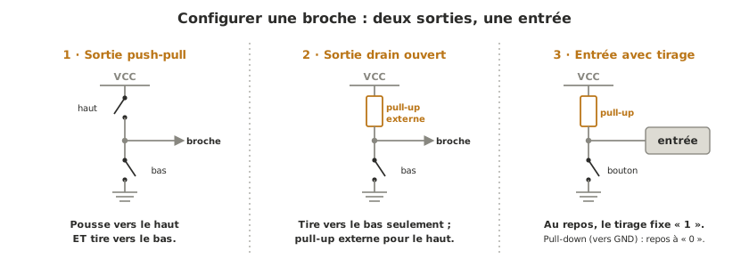
One and the same pin can serve as an input or as an output. The program fixes its role at start-up. Beyond direction, two settings decide how the pin behaves electrically: the pull resistor on an input and the output type.
| Mode | Direction | What it does | State at rest | Typical use |
|---|---|---|---|---|
| High-impedance input (INPUT) | input | reads the level without loading the circuit | floating (undefined) | pin driven by a clean signal |
| Input with a pull resistor (INPUT_PULLUP) | input | an internal resistor sets the rest state | ”1” (pull-up) or “0” (pull-down) | button, switch |
| Push-pull output (OUTPUT) | output | actively forces high and low | set by the program | LED, control signal |
| Open-drain output | output | only pulls low | ”1” with an external pull-up | shared bus (I2C), common alarm line |
The names in brackets (INPUT, INPUT_PULLUP, OUTPUT) are the constants you meet on the Arduino side: they are vocabulary labels, and the code itself is covered in the Arduino GPIO tutorial. The other families have their own tutorial — ESP32, MicroPython, Raspberry Pi — with the same concept and a different syntax.
Push-pull or open drain? A push-pull output is the common case: it ties the pin to the supply for a “1” and to ground for a “0”, forcing both levels cleanly. An open-drain output can only pull the pin low. For the high state it releases the pin and relies on an external pull-up resistor to bring it back up towards the supply. That behaviour, crippled as it looks, is exactly what you want when several components share one line: none of them actively drives the high state, so none of them fights the others. That is the principle behind I2C and behind common alarm lines.
The floating-input trap — why a button needs a pull resistor
An input in high impedance draws almost nothing: that is its virtue when it reads an already clean signal, and it is also its trap. If the pin is tied to nothing definite, it behaves like a small antenna and picks up the ambient electrical noise: it floats, and reads an unpredictable level, now “0”, now “1”.
That is exactly what happens with a naively wired button. When the button is pressed, it ties the pin to a definite voltage. But when it is released, the pin is no longer tied to anything: it floats.
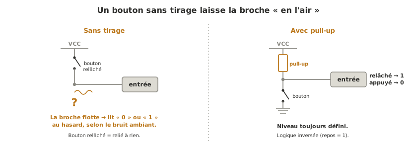
The remedy is a pull resistor, which forces a clean level at rest. A pull-up (to the supply) holds the pin at “1” as long as the button is released, and pressing forces it to “0”: the logic is then inverted (rest = 1, pressed = 0), which often catches people out on their first wiring. A pull-down (to ground) does the opposite. Most microcontrollers carry a pull-up that the program can switch on (INPUT_PULLUP), which saves adding an external resistor and makes it the simplest reflex for a button.
Pin states at power-up
At the exact moment the system is powered, the program has not run yet: its setup function has not executed, so no pin is configured. During that short window, almost every microcontroller leaves its pins as high-impedance inputs, that is to say floating.
The danger is not for the input pins, but for whatever is wired as an output. If a pin drives a relay, a motor or a buzzer, and nothing holds its level during boot, the actuator can go into an uncontrolled state: a relay that clacks, a motor that jerks, an output that switches on for a fraction of a second before the program takes over. On a robot arm or a machine, that kind of transient is a real safety question.
The remedy is not in the code, precisely because the code is not there yet: it is hardware. You add an external pull resistor on the critical outputs, sized to force the actuator into its safe state (usually off) until the microcontroller has taken control. Relying on the software setup alone to put an output into a safe state means ignoring the boot window. Putting it to work — pins to avoid at start-up, wiring the safety pulls — is covered in the GPIO at start-up tutorial.
Pitfalls
Forgetting the pull resistor on an input. An input pin left floating reads noise. Any button or switch needs a pull-up or a pull-down — internal (INPUT_PULLUP) for preference, external otherwise.
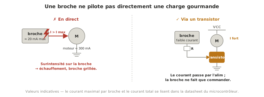
Drawing too much current from a pin. A pin supplies a few tens of milliamps at best. A motor, a relay coil or a cluster of LEDs asks for far more. Wiring a hungry load straight onto the pin puts it into overcurrent and destroys it. You go through a transistor, a driver or a relay module, which let the supply provide the current.
Confusing logic and electrical level. A logic “1” is not necessarily 5 V: it is the high level of that particular part, which may be 3.3 V. Making two pins of different voltages talk to each other is a subject of its own, covered in logic levels.
Believing an output is in a defined state from power-up. Before the program configures its pins, they are floating, a trap for outputs driving an actuator (see the section on states at power-up).
Forgetting the inverted logic of a pull-up. With a pull-up, rest reads “1” and a press reads “0”. Reading the pin as if “pressed” meant “1” gives inverted behaviour, a classic first-attempt bug.
See also
- Input and output — the family of peripherals the GPIO is the elementary brick of
- Logic levels — what real voltage hides behind a “0” and a “1”, and how to bridge 3.3 V and 5 V
- Microcontroller — the chip that carries the GPIO pins
- ADC — the input counterpart for continuous quantities (reading a varying voltage)
- PWM — the output counterpart, metering a command rather than forcing it on or off
- Interrupt — reacting at once to a change of state on a pin, without polling it in a loop
- Communication buses — where open drain comes into its own (I2C, shared lines)
- Arduino — GPIO — putting it to work on Arduino (button, LED, code and wiring)
- Arduino — GPIO at start-up · MicroPython — GPIO at start-up — pin states at boot in practice, safety pull resistors
- ESP32 — GPIO · MicroPython — GPIO · Raspberry Pi — GPIO — the same brick in the other families