Reading a schematic means working through a circuit diagram to understand what the circuit does: identifying its functions, following the path of the signals and of the energy, and checking that it hangs together — before wiring anything, debugging, or backing a choice. It is a reading skill, and it goes with the functional block diagram (which says which functions) and with the datasheet (which details each part).
What is it for?
In a project you run into schematics all the time: the documentation of a module, the application circuit in a datasheet, a teammate’s drawing. Being able to read one lets you:
- wire a module properly instead of copying it pin by pin without understanding it;
- debug — when nothing works, the schematic tells you where the current should be going;
- check a design before ordering a board or parts;
- get something out of a datasheet — its typical circuit is a schematic you have to be able to decode before you can use the part.
Without this skill you connect wires and hope, and the smallest problem becomes impossible to diagnose. Reading a schematic turns a drawing into an understanding of how the thing works.
Step by step
An efficient read always follows the same order: frame the supply, break it into functions, identify, follow the signals, check.
1. Locate the supply and the ground
Every circuit lives between two potentials: the supply (labelled VCC, VDD, or straight out as +5 V / 3V3 depending on the drawing, and drawn at the top by convention) and the ground (GND, at the bottom). Start by locating them and noting the voltage (3.3 V? 5 V? 12 V?). That is the frame everything else is read in, and the first source of incompatibility (see logic levels). A schematic often has several: a power rail and a logic rail, sometimes symmetric rails (+15 V / −15 V) for analog work — spot each rail, and note what powers what.
2. Break it into functional blocks
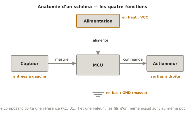
Group the parts by function in your head: supply, processing (the MCU), inputs (sensors), outputs (actuators). This is the functional block diagram applied to a real schematic. You find the same four functions again, this time as actual parts.
3. Identify each part
Every symbol is a part with a reference (R1, C2, U1, D1) and a value (10 kΩ, 100 nF). Learn the common symbols — resistor, capacitor, diode and LED, transistor, integrated circuit. For an integrated circuit, the role of each pin is in its datasheet.
4. Follow the signals: input → processing → output
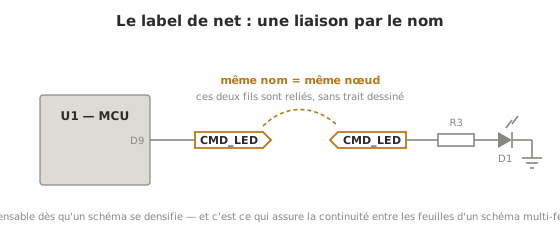
Follow the wires. By convention, information travels left to right: inputs on the left, outputs on the right. Trace a signal from its source (a sensor) to its destination (an actuator), passing through the processing. Watch out for net labels: two wires carrying the same name are connected, even if no line joins them on the drawing.
5. Check that it hangs together
A few common-sense checks close the read. Does every input have a source and every output a load? No direct VCC–GND connection (a short)? Are the pull resistors (pull-up / pull-down) and current-limiting resistors there? Are the decoupling capacitors close to the integrated circuits? Is the protection stage there (fuse, reverse-polarity diode)? Are the voltages compatible all the way through (see logic levels)? A schematic that hangs together passes these six questions.
A worked example
Let us apply the method to a small circuit: a sensor read by an MCU that drives an LED.
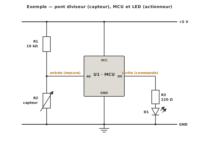
- Supply. Two rails:
+5 Vat the top,GNDat the bottom. The whole circuit runs at 5 V. - Blocks. Three functions appear: a voltage divider on the left (sensor input),
U1in the middle (processing), the LED on the right (actuator output). - Parts.
R1(10 kΩ, fixed) andR2(the sensor, a variable resistor);U1, the MCU;R3(220 Ω);D1, the LED. - Signals. When the resistance of sensor
R2changes, the voltage at the midpoint changes. That voltage is read by analog inputA0of the MCU (an analog-to-digital conversion). The MCU decides (its logic) and drives outputD9, which lights the LED. - Hangs together.
R3limits the current throughD1(without it the LED would burn out), and the voltage divider turns the change in sensor resistance into a voltage. An MCU does not read ohms, it reads volts onA0. The circuit stands up.
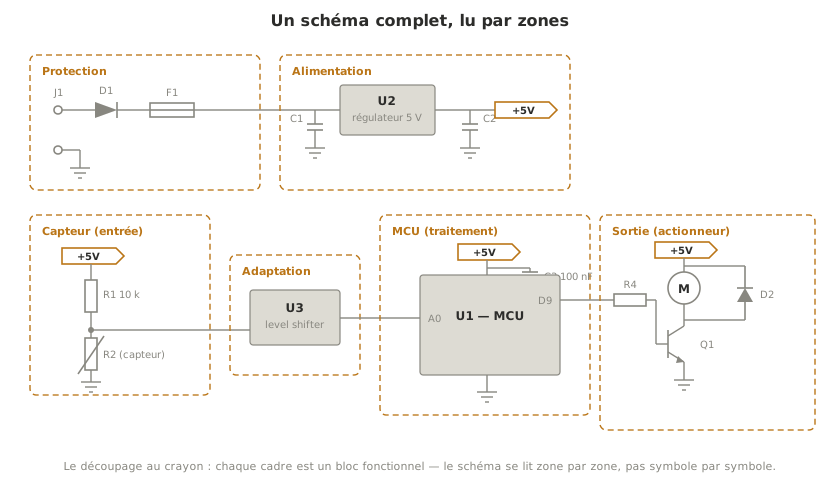
On a real schematic, with a lot more on it, the same breakdown is done in pencil: boxing off the functional zones (protection, supply, input, level shifting, processing, output) turns a page of symbols into a readable map.
Pitfalls
Wiring without understanding. Copying a schematic pin by pin “because it works in the example” leads to circuits you have no way of fixing. Read first, wire second.
Skipping the supply step. Until you have located VCC and GND and noted the voltage, you are reading the schematic with no frame. That is where you start, not with the exotic parts.
Confusing lookalike symbols. A fixed resistor and a variable one, a polarised capacitor and a non-polarised one, a diode and an LED: close symbols, different roles. When in doubt, check the reference and the datasheet.
Ignoring net labels. On a schematic with any amount on it, a lot of the connections go through signal names rather than lines. Same name means same node, even with no wire drawn.
Forgetting the “invisible” parts. The current-limiting resistor for an LED, the pull-up on a button or on an I2C bus, the decoupling on an IC: leaving them out is a mistake, not a detail.
Confusing schematic and layout. The schematic describes the electrical connections (what is connected to what). It says nothing about the physical placement of the parts on the board. They are two distinct views of the same circuit.
Special case — Multi-sheet schematics and the application circuit
A large schematic spreads over several sheets linked by net labels (or off-page connectors): no wire crosses the pages, it is the identity of the names that carries the connection through. On top of that, almost every datasheet gives an application circuit (or typical application): a ready-made schematic showing the recommended wiring for the part. Being able to decode it is already knowing how to use the chip, half the integration work.
See also
- Functional block diagram — the view by function, upstream of the schematic
- Reading a datasheet — to identify what the pins do and to read an application circuit
- Logic levels — voltage compatibility, the key check of step 5
- Analog-to-digital conversion — how the MCU reads a sensor voltage
- Flowchart — the decision logic behind the command
- Measuring instruments — measuring on the real circuit what the schematic describes
- Printed circuit board — turning the checked schematic into a manufacturable board