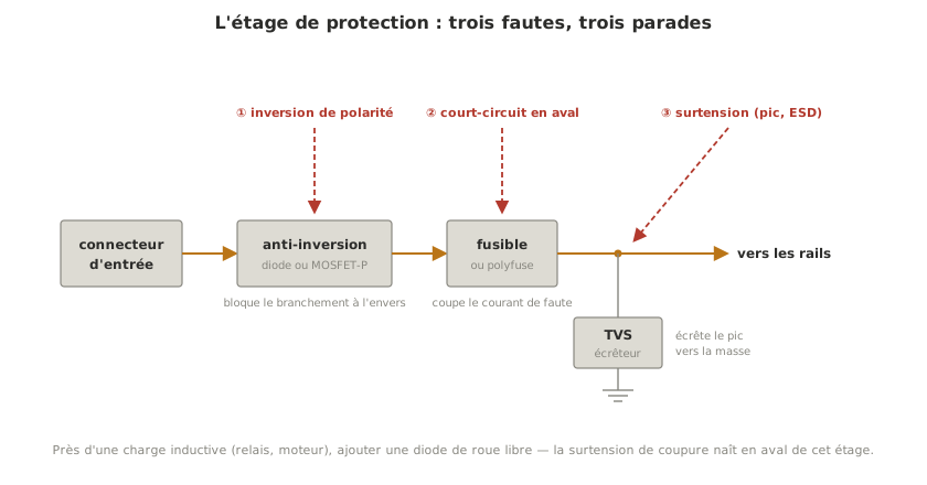
Electronic protections make the common faults — short circuit, reverse polarity, overvoltage, electrostatic discharge — non-destructive: the fault costs a fuse or a second of fallback, not a board. They are designed on the assumption that someone will get it wrong when plugging in, and they sit at the head of the power supply, between the input connector and the rails.
What is it for?
Over the life of a project, all three faults will eventually happen: a wire that slips and shorts, a connector plugged in backwards one tired evening, a voltage spike when a motor is switched off. The question is not whether, but when, and what the fault will cost. Protected, it costs a fuse worth a few cents and five minutes. Unprotected, it costs a component, sometimes the whole chain it was feeding, and the days of delay to re-order. The design rule fits in one sentence: expect the mistake, and make it a non-event.
How do you protect?
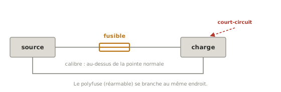
Against a short circuit: limit the current. The fuse (5×20 mm glass in a fuse holder) cuts permanently above its rating, chosen above the normal peak of consumption, never below. The polyfuse (resettable PTC fuse) resets itself once it has cooled, handy during bring-up. And for the first tests of a new build, the electronic current limit of a bench power supply (constant-current mode) turns a short circuit into a simple fallback: that is the protection to set before plugging anything in.
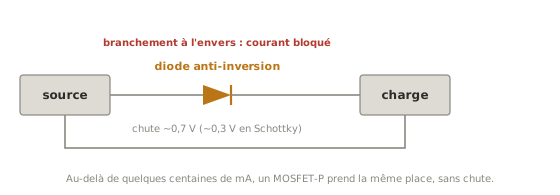
Against reverse polarity: block or key it. A series diode blocks a reversed connection: simple, but it drops ~0.7 V (~0.3 V for a Schottky) and heats up at high current. A P-MOSFET wired as a reverse-polarity block does the same job with a negligible drop: it is the clean solution beyond a few hundred mA. The best protection, though, remains mechanical: a keyed connector (XT60, polarised JST) makes the fault physically impossible, and it is chosen at design time.
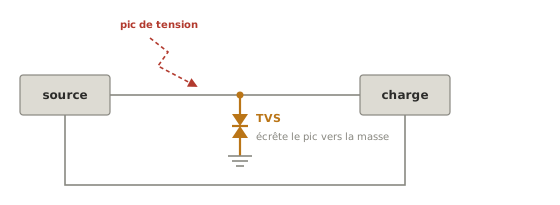
Against overvoltage: clamp it. A TVS diode (or a Zener) fitted in parallel clamps voltage spikes — a transient from the source, the kickback when a load is switched off — to ground, before they reach the circuits. It is chosen at the voltage of the rail: transparent in normal operation, conducting as soon as the voltage runs away.
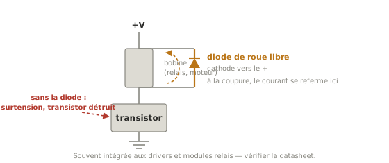
Against the switch-off overvoltage of inductive loads: the flyback diode. A coil — relay, DC motor, solenoid valve — opposes changes in its current: when the transistor driving it opens, it generates an overvoltage of several tens of volts to keep its current flowing, and it is the transistor that takes the hit. A flyback diode fitted in reverse across the coil offers a recirculation path: the current dies away gently, the transistor survives. It is mandatory on every driven inductive load, and often already built into off-the-shelf drivers and relay modules, so check the datasheet.
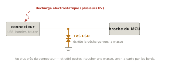
Against electrostatic discharge (ESD): protect the exposed lines — and the hands. A charged human body carries several kilovolts: touching a pin is enough to punch through a CMOS input, either at once or by weakening it for later. On the circuit side, ESD-specific TVS diodes go on every line accessible from the outside (USB connector, terminal block, buttons). On the handling side, the habits matter as much as the components: touch a ground before picking up a board, hold boards by their edges, keep components in their antistatic bags.
The complementary parts. Three protections often exist already in the system, and are worth knowing so as not to duplicate them needlessly: the thermal protection built into modern regulators (they shut down when they overheat); the brown-out detector of the microcontroller, which holds it in reset when its supply falls below a threshold instead of letting it run off the rails; and the BMS (battery management system) of lithium batteries, essential against overcharge and deep discharge. Finally, when power and control have to be firmly separated, an optocoupler isolates the two worlds galvanically: no electrical path, the signal travels as light.
Tip
Proven references — 5×20 glass fuse plus fuse holder; resettable PTC polyfuse; Schottky 1N5819 or SS34 (light reverse-polarity blocking, fast flyback); 1N4007 (relay flyback); P-MOSFET AO3401 (small currents) or IRF4905 (high currents); SMBJ series TVS chosen at the rail voltage; for ESD on data lines, USBLC6 or the PESD family. These are stable, common families: start from them, check availability and read the datasheet before ordering.
Example — the 3-axis arm
On the arm of the running example, the input stage chains the three defences: a reverse-polarity MOSFET guards the whole system against a reversed connection, a fuse rated on the peak of the three stepper motors protects the power rail, a TVS near the connector absorbs transients from the source. The flyback diodes of the motors are already built into the A4988 drivers, a frequent case: check in the datasheet what the component already includes before adding your own. The 5 V logic, behind its regulator, ends up doubly sheltered.
Pitfalls
Under-rating the fuse. A fuse at the level of the normal peak blows the first time a motor starts. The rating goes above the expected peak, and below the current that destroys the wiring.
Replacing a blown fuse with a bigger one. A fuse that blows is reporting a fault. Over-rating it removes the defence, not the fault: the next part upstream will play the role of the fuse.
Relying on a series diode at high current. At 2 A, an ordinary diode dissipates ~1.4 W and steals 0.7 V from the rail. Beyond a few hundred mA, the P-MOSFET is the answer.
Forgetting the flyback diode on an inductive load. A relay or a motor driven by a transistor with no flyback diode: the transistor dies at switch-off, first time or hundredth, but it dies.
Picking a board up by its pins. The kilovolts of an electrostatic discharge are not even felt, but the component feels them. By the edges, after touching a ground.
Believing that the input stage protects everything. It protects the supply, not the pins: a GPIO that is shorted or that receives too high a voltage is protected locally: series resistor, and compatibility of logic levels.
See also
- Designing a power supply — the architecture note of which this stage is one of the moves
- Logic levels — overvoltage on the signal side (5 V on a 3.3 V pin), cousin of the one treated here
- Designing a board (PCB) — fitting the protection stage onto the board
- Safety and quality — the safety of people, a subject distinct from protecting the hardware
- Electromagnetic compatibility (EMC) — ESD and overvoltage protection is the hardware side of EMC immunity