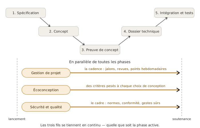
Safety and quality is a cross-cutting thread that watches over two inseparable demands of the mechatronics project: protecting people — users and team alike — and keeping the documentary trace that makes the technical choices justifiable. Like project planning and tracking and eco-design, it does not start at a particular phase. It settles in continuously, from technical specification through to integration and testing. It connects to the neighbouring disciplines (mechanical engineering, manufacturing) and to the standards expertise held by the specialist teaching staff.
The right mindset
The temptation with safety and quality is to reduce it to an addendum at the end of the report — a paragraph on CE standards, a quick mention of the PPE that was worn. Resist it. Safety and quality is neither a box to tick nor a file produced at the end of the project: it is vigilance built into every technical decision and a discipline of traceability that runs across the whole semester. The key skill this framework page teaches: protect without paralysing, record without drowning — carrying what belongs to teaching expertise in electronics and embedded software (safe architecture, code reviews, version traceability, test plan), naming and delegating what belongs to detailed regulatory compliance or to specific trade risks (low voltage, EMC, ISO 12100, machining) to the disciplines that own them.
Goal
Keep a safety and quality approach alive, built into the technical choices and into the pace of the project:
- product safety anticipated through user risk analysis (stored energy, contact, moving parts) and embodied in the architecture (emergency stop, guards, isolation, hard stops)
- project safety guaranteed by firm workshop and handling rules (training beforehand, PPE, working in pairs)
- documentary quality held by a review plan, version traceability on the hardware (PCB) and the software (firmware under Git), and a safety file spread across the deliverables of the five phases
- an explicit connection to the standards courses run by neighbouring disciplines (CE marking, the Low Voltage Directive, EMC, ISO 12100)
All of this runs across the deliverables of the five phases of the V-model, rather than sitting in a deliverable of its own.
Method
Safety and quality holds three fronts that become active in parallel from the technical specification onwards and stay active until the final presentation: protecting the end user (product safety), protecting the team while it builds (project safety), recording what was done and why (documentary quality). These three blocks do not run in a fixed order. They feed one another and turn continuously, with safety and quality woven into each.
1. Product safety (the end user)
Identify the user risks from the technical specification onwards. Every mechatronic system carries sources of risk: kinetic energy in the moving parts, stored electrical energy, heating, sharp or pinching parts, emissions (light, sound, radiation). The analysis is carried out at technical specification, in the pieuvre (the “octopus” diagram, the French function-mapping tool) through the user safety FC, and is completed when the architecture is settled at concept, where the moving parts and the energy levels become precise. A risk analysis of the AMDEC kind (the French acronym for FMEA), or a scaled-down teaching variant, lists the possible failure modes, their severity, their likelihood and the safeguard planned for each. This page does not go through the method here. It is set out on the AMDEC page: level of analysis, modes, effects and causes, severity × occurrence × detection rating. What this page carries is how it fits into the cycle of the project: when to run it, on what, and what to do with its conclusions.
Put safety into the architecture, not on top of it. Once the risks are identified, the safeguards take shape in the technical choices: an emergency stop wired to cut power directly (not through the firmware, which can crash), galvanic isolation on the operator interfaces, mechanical hard stops on top of the software limits, fuses sized for what is actually needed, a guard over the areas where contact is a risk. The architectural rule: no critical safety function should rest on software alone. A firmware fault must not be able to compromise user safety. This discipline is one of the main markers of an engineered system against an amateur prototype.
Check it at integration, not at commissioning. Product safety is verified during the integration and testing phase, on the same footing as the functions of the CdCF. The safety tests are part of qualification level 4: emergency stop tested in real conditions with a part in motion, hard stops checked by simulating an overrun, isolation measured with an ohmmeter. A system that has never tested its emergency stop does not have an emergency stop. It has a red button.
Name and delegate what belongs to detailed regulation. CE marking compliance, the Low Voltage Directive, electromagnetic compatibility (EMC), ISO 12100 on machinery safety, insulation classes, IP and IK ratings: these standards carry an expertise of their own, held by the ESE disciplines and by the courses that cover them. This page names them where they apply to the student project and brings them in as constraints in the pieuvre and the CdCF, but does not duplicate them. A teaching project is not aiming for real CE marking, but it does have to be able to recognise that a given component falls under a given directive, and to point to the page or the course that covers it.
Example: 3-axis arm project
User risks identified from the technical specification onwards: pinching at the three moving joints, motor torque high enough to injure a trapped finger (steppers at around 0.5 Nm while holding), electrical energy at 24 V DC stored in the supply bus capacitor (no risk of electric shock at 24 V, but a tool short-circuit throws a spark and burns). Safeguards built in at concept: an emergency stop, a red mushroom head cutting the 24 V supply directly (checked at qualification level 4 during integration in week 14), mechanical hard stops through limit switches doubling the software limits, a printed PLA guard covering the operator pinch points, a fuse on the 24 V input, sized on the peak draw of the three motors. The arm remains a teaching prototype, with no CE ambition, but the pinching risk is treated as a real risk rather than a finishing detail.
Deliverable 1/3 — Safety and quality
Product safety anticipated and embodied, evidenced by:
- Ongoing: a user safety criterion present in the pieuvre (safety FC) and in the concept decision matrices, architectural safeguards documented in the technical design file
- At milestones: safety tests (emergency stop, hard stops, isolation) run and recorded at qualification level 4 during integration and testing
2. Project safety (the team while it builds)
Identify the risks on the team side from kick-off. A mechatronics project puts the team in contact with risks that belong to building things: electrical risk while wiring and testing under power (24 V is generally manageable, but there is still soldering on the supply and handling boards while live), mechanical risk on the workshop machines (drill, mill, milling machine for single-sided PCBs), mild chemical and respiratory risk (glass fibre dust when milling a PCB, solder flux), risk to the eyes (flying debris when drilling and milling). The risk is not an industrial risk, it is a teaching one, but it is real and it has to be named. This page puts those risks into the risk matrix on the same footing as the technical or schedule risks, so that they stay visible throughout the project and get revised at every phase review.
Three rules that are not negotiable, day to day. Beyond the standard PPE (goggles when drilling, gloves where relevant, closed shoes, long hair tied back), three rules apply as absolute guard rails of a student project:
-
No work on 230 V without a supervisor present. The 24 V low voltage of the motors and microcontrollers can be handled independently once the initial training is done. Mains voltage (mains power supplies, transformers, workshop lines) requires a teacher or technician physically present, with no exception and no waiver for calendar pressure.
-
No use of a machine without training first. Every workshop machine (pillar drill, mill, PCB milling machine, specific fablab equipment) requires initial training signed off by whoever is responsible for the equipment. The training is not a formality, it is what makes the use possible. A team that meets a machine mid-project has to schedule that training as a task in the Gantt chart, not improvise it standing in front of the machine.
-
Never alone in the workshop. A minimum of two people is not a comfort, it is the condition for being able to call for help if something happens. Working alone in the workshop or the fablab, even for five minutes, is forbidden. This rule takes precedence over every scheduling constraint.
PPE is not a detail. Safety goggles when drilling, when machining and when milling a PCB; closed shoes in the workshop; long hair tied back near rotating machines; clothing kept close to the body. These instructions do not belong to this page as such. They are carried by the workshop supervisors and the manufacturing courses. What this page does is build their discipline into the project schedule (workshop slots identified, training scheduled beforehand) and make sure they are not skipped under calendar pressure.
Working with the people responsible for the equipment. The fablab supervisor, the machine shop supervisor, the electronics lab supervisor are not service providers. They are trade contacts who carry the safety culture of their area. The team meets them early, understands their instructions, and takes them on board as structuring constraints of the project. A team that waits until the last week to approach the fablab supervisor about 3D printing finds out about lead times, settings and rules too late. A team that plans ahead can build those constraints in from concept onwards.
Example: 3-axis arm project
In the team risk matrix in week 2, three project risks identified — electrical risk on the 24 V supply soldering (safeguard: work in pairs, plus soldering training in week 3), mechanical risk on machining the aluminium joint (safeguard: mill training in week 4, plus a supervisor present at all times), mild respiratory risk from the glass fibre dust when milling the single-sided PCB (safeguard: extraction and goggles, supervisor present at all times for the milling machine). Three rules held without exception across the 15 weeks: no 230 V without a supervisor, no machine without training, never alone in the workshop. A waiver considered in week 12 (one teammate alone to finish a soldering job on a Sunday afternoon) was refused by the team itself. The delay was made up on the Monday morning working in pairs, with no damage to the overall schedule.
Watch out
A project safety rule is never relaxed under schedule pressure. A delay is an acceptable cost. A workshop accident is not. When the calendar is tight, the right move is to cut the scope (deliver a minimal version, push an option back) or to alert the supervisor for a ruling — never to bend the handling rules. A team that picks up this discipline in a teaching project will carry it into working life. A team that learns to work around it will reach for the same reflex when the stakes are higher.
Deliverable 2/3 — Safety and quality
Project safety held for the whole length of the project, evidenced by:
- Ongoing: three rules held without exception (no 230 V without a supervisor, no machine without training, never alone in the workshop), project risks present in the risk matrix and revised at every phase review
- At milestones: training on the machines scheduled ahead of the build phases, sign-off by the person responsible for the equipment recorded
3. Documentary quality
A review plan set out from the technical specification onwards. Documentary quality rests first of all on a schedule of reviews identified from the technical specification onwards and held to until the final presentation. That schedule is structured by the milestones of the V-model: CdCF review (closing technical specification), concept review (closing concept), PoC review (closing proof of concept), technical design file review (closing the technical design file), qualification review (closing integration), final presentation. Every review is announced, prepared through the deliverables of the phase, and recorded in a set of minutes that mark the transition. This cadence is largely steered by project planning and tracking. Documentary quality fits into it, it does not create a parallel cadence.
Version traceability on hardware and software. Every change to a structuring deliverable has to be datable and explainable. Three canonical practices on the electronics and embedded software side:
-
A revision number silkscreened on the PCB. Every PCB carries a “Rev A” or “Rev B” marking silkscreened directly onto the board. Every change to the layout gets a new number. The revision is recorded in the technical design file, with what changed and why. A PCB without a revision number becomes useless for late debugging, because the team no longer knows which version is on the bench.
-
Git tags at each milestone for the firmware. The embedded code is versioned under Git. At each major milestone (PoC, technical design file, qualification, final presentation) a tag is placed on the corresponding commit. That discipline makes it possible to go back precisely to the qualified version of the firmware if a regression is introduced later. A project without Git does not hold documentary quality. A project with Git but no tags stays fragile.
-
A cross code review at each milestone. Before each milestone, a review between teammates (at minimum) or with the supervisor (ideally) looks over the critical pieces of the firmware — safety functions, interrupt handling, the state machine. The review is not looking for perfection. It targets the obvious defects that an outside eye catches immediately and that the author of the code, too close to it, no longer sees.
A structured safety file that holds from one end to the other. The safety file is not a single section of the report. It is spread across the deliverables of the five phases: user risk analysis at technical specification, architectural safeguards at concept, hardware checks at proof of concept, detailed drawings in the technical design file, safety qualification tests at integration. At the final presentation, that file reads as a coherent thread running through the project, not as a late chapter. The proof of documentary quality is that the panel can follow the thread without a break.
An explicit connection to the standards that are named. Documentary quality brings in the standards relevant to the project (RoHS, REACH, WEEE on the eco-design side, CE marking, the Low Voltage Directive, EMC and ISO 12100 on the product safety side), but does not duplicate them. For each standard touched, the documentary trace takes the form of a line in the technical design file naming the standard, the component or subsystem concerned, and the pointer to the course or the page that covers it. The rule: name it to record it, delegate for the depth.
Example: 3-axis arm project
Review plan set out in week 2 and held without slippage: CdCF review (week 3), concept review (week 5), PoC review (week 6), technical design file review (week 11), qualification review (week 14), final presentation (week 15). Hardware traceability: single-sided PCB milled in-house at the school, Rev A silkscreened in week 9, Rev B in week 10 after aligning with the technical design file (three 100 nF decoupling capacitors added), recorded in the technical design file. Software traceability: Git repository set up in week 2, tags
v0.1-poc(week 6),v0.2-dossier(week 11),v1.0-qualif(week 14),v1.0.1-soutenance(week 15). Cross code review at each tag, 30 minutes minimum, focused on the interrupt handling of the emergency stop and the state machine of the hard stops. Safety file spread out: risk analysis at technical specification (three user risks), safeguards at concept (emergency stop, hard stops, guard, fuse), verification at qualification (four safety tests recorded). Standards named in the technical design file: one line per standard touched (RoHS on components, EMC mentioned without aiming at certification, ISO 12100 named for the culture).
Tip
Record it when the decision is made, not at the end of the phase. The discipline of traceability collapses when it is put off until the report is written. Justifications forgotten over two weeks do not get reconstructed faithfully. The practice that holds: for every decision settled in a team meeting, one sentence written into the document concerned the same day (decision matrix, technical design file, commitment log). A well-kept set of weekly minutes is often enough to carry that trace. Documentary quality downstream then becomes nothing more than a formatting job.
Deliverable 3/3 — Safety and quality
Documentary quality held for the whole length of the project, evidenced by:
- Ongoing: version traceability on the PCBs (silkscreened revision numbers) and the firmware (Git commits and tags at each milestone), code reviews at the milestones, safety file spread across the deliverables of the five phases
- At milestones: one set of review minutes at each milestone (CdCF, concept, PoC, technical design file, qualification, final presentation) marking the transition and recording the decisions
Common pitfalls
- Putting safety off to the end of the project. User risk analysis is not carried out at integration. It is set out at technical specification, in the pieuvre through the user safety FC, and settled at concept. Product safety added late amounts to a cosmetic addendum that weighs on no technical choice.
- Resting a critical safety function on software alone. A firmware fault must not be able to endanger the user. The emergency stop is wired to cut power directly. Software limits are doubled by mechanical hard stops.
- Testing the emergency stop too late, or not at all. A system that has never tested its emergency stop does not have one, it has a red button. The test is part of safety qualification at integration, in real conditions with a part in motion.
- Confusing project safety with product safety. The two fronts do not use the same tools or the same contacts. Project safety is about the team while it builds (PPE, training, workshop rules). Product safety is about the end user (architecture, emergency stop, compliance).
- Bending the workshop rules under schedule pressure. No 230 V without a supervisor, no machine without training, never alone: these rules do not relax. A delay is an acceptable cost. An accident is not.
- Meeting the fablab supervisor or the workshop constraints too late. A team that approaches the person responsible for the equipment in the week it needs them finds out about lead times, prior training and settings too late. Plan at least two weeks ahead.
- Keeping the trace after the fact, when the report is being written. Justifications for decisions forgotten over two weeks do not get reconstructed faithfully. The trace is written on the day of the decision, in the document concerned.
- Versioning the firmware without placing tags. A Git repository with no tags at the milestones does not let you go back precisely to the qualified version. Version traceability is not the existence of the repository, it is the discipline of tagging the stable points.
- A PCB with no silkscreened revision number. A team that produces several revisions without telling them apart physically loses track of what is on the bench. Silkscreening “Rev A” and “Rev B” is trivial to add to the layout and indispensable for late debugging.
- Encroaching on the detailed standards owned by ESE. CE marking, EMC, ISO 12100 and insulation classes carry an expertise of their own. This page names them and points to the courses that cover them. An argument about standards built in-house, without a check, weakens the report at the final presentation.
- Confusing the safety file with a dedicated chapter. The safety file is spread across the deliverables of the five phases (analysis, safeguards, checks, drawings, tests), not gathered in one late chapter. Its quality is measured by how coherent the thread running through the project is.
During this phase, on the team side
Safety and quality connects to the other two cross-cutting threads and delegates explicitly to several courses and contacts held by neighbouring disciplines. Three connections structure this section.
-
Build it into the project cadence. Project planning and tracking steers the safety and quality thread just as it steers eco-design. Phase reviews include a safety and quality point (five to ten minutes is enough): is the emergency stop still in the architecture? Do the standards named at technical specification still apply? Is the safety test plan up to date? Are the three workshop rules being held? Without that regular presence at the review, the thread drifts off the radar within weeks.
-
Build it into the risk matrix. Product safety risks (a safety part failing, a compliance defect, an unplanned public being exposed) and project safety risks (a workshop accident, a training session unavailable, a dependency on someone responsible for equipment who is away) appear in the risk matrix on the same footing as the technical or schedule risks. Same attributes (likelihood, severity, response), same update cadence at every phase review. The risk matrix is one of the most visible supports documentary quality has.
-
Steer without smothering. Safety and quality is not the project, it goes alongside it. A teaching project is not aiming for real certification (CE, ISO and the rest). It is aiming for a living safety and quality culture that prepares students to meet those things in industry. The non-smothering rule: do not turn the project into an exercise in standards where every technical choice is bent to serve a simulated compliance. Standards get named, and brought in as constraints in the pieuvre and the CdCF, but they do not dictate the project.
Specific to this thread, explicit delegation to neighbouring disciplines on two fronts. On the detailed standards side: CE marking, the Low Voltage Directive, EMC, ISO 12100, insulation classes, IP and IK ratings, all carried by the ESE courses and the specialist teaching staff. On the manufacturing side: the fablab supervisor for 3D printing and for handing over STL files, the workshop supervisor for machining and soldering, the electronics lab supervisor for milling single-sided PCBs and for handling 24 V. These people carry the safety culture of their area. This page connects to it, it does not duplicate it.
Wrap-up
By the end of the project, safety and quality will have run through the five phases of the V-model without a break. Every phase will have contributed an analysis, a safeguard, a check or a trace. Safety and quality done well does not show as an add-on. It is measured by how coherent the safety thread stays between the risk analysis at technical specification and the qualification tests at integration, and by how readable the documentary trace is for a panel that has to follow it without a break. See the project path hub to place this framework page back in the V-model as a whole, and the project planning and tracking and eco-design pages for the other two cross-cutting threads it works alongside.
See also
- Project path hub
- Risk matrix (carries the safety and quality risks)
- Project planning and tracking (cross-cutting thread, steers safety and quality)
- Eco-design (cross-cutting thread, regulatory overlaps on RoHS, REACH and WEEE)
- AMDEC (the product risk analysis method)
- CE marking (delegated to the standards courses)
- Low Voltage Directive (delegated to the standards courses)
- Electromagnetic compatibility (delegated to the standards courses)
- ISO 12100 (delegated to the standards courses)
- Code review (a software quality practice)
- PPE (personal protective equipment)