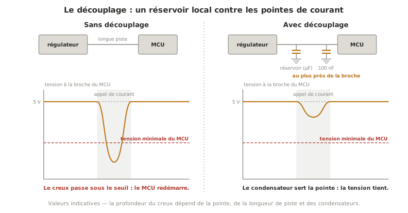
Decoupling means placing capacitors as close as possible to each component, to serve its current peaks locally, those peaks being too brief for the power supply to catch up with them. Without it, every peak digs into the voltage at the component’s pin — enough to spoil a reading or to reset a microcontroller — and the fault is all the nastier for being invisible on a multimeter.
What is it for?
A regulator holds the voltage of its rail, but it does not react instantly. And above all, the track or the wire between it and the component has a resistance and an inductance that oppose rapid changes in current. When a component draws a brief peak — an output switching, a radio module transmitting, a motor starting —, the current cannot build up quickly enough through the track: the voltage at the pin collapses locally for a few microseconds, then everything settles again.
A few microseconds are all it takes, though: a microcontroller resets, an ADC conversion returns a nonsense value, a radio module drops its packet. These are the “unexplained” intermittent failures par excellence. The multimeter, far too slow, shows a perfectly healthy rail. Only the oscilloscope shows the dip.
The decoupling capacitor is the answer: a local reservoir, charged to the rail voltage, which supplies the peak on the spot for as long as the current takes to build up from the supply, then recharges.
How to decouple
Two stages that complete each other. A bulk capacitor (an electrolytic of 100 to 470 µF) takes the slow, large variations. It goes at the input of a stage or across a heavy consumer (a motor driver). A 100 nF ceramic capacitor answers the fastest variations. It goes right against every supply pin of every integrated circuit. Neither replaces the other: the bulk is too “slow” for fast edges, the ceramic too small for large demands.
As close as possible, always. How well decoupling works is measured in millimetres: on a printed circuit board, the 100 nF goes against the pin; on a breadboard, in the holes immediately next to the component. Ten centimetres away at the end of a wire, the inductance of the wire cancels its effect, so you may as well fit nothing at all.
One 100 nF per chip, not one for all of them. Decoupling is local by nature: every integrated circuit (microcontroller, driver, sensor, memory) gets its own. The application circuits in datasheets say so every time. And commercial boards, such as an Arduino board, already come covered.
Tip
Tried and tested parts — 100 nF X7R ceramic (the absolute standard, worth buying by the bag), aluminium electrolytic 100 to 470 µF for the reservoirs, 10 µF ceramic as a compact addition. Take a voltage rating of at least twice the rail (25 V on a 12 V rail), and read the application circuit in the datasheet of the component you are decoupling: it gives the values expected.
Example — the 3-axis arm
On the running example arm, each A4988 driver gets its own bulk capacitor (100 µF, required by the driver’s datasheet): the three stepper motors draw their current in peaks, at every step. The microcontroller and each encoder get their 100 nF at the supply pin. Without the bulk capacitors at the drivers, starting the three axes at once digs into the power rail, the dip travels, and the microcontroller resets mid-movement, a textbook intermittent failure, invisible on a multimeter.
Pitfalls
Decoupling from a distance. A capacitor at the end of a long track or a flying wire decouples nothing: the inductance of the path cancels its effect. The distance is counted in millimetres.
One big capacitor for the whole board. The central reservoir does not answer the fast peaks of each chip. The two stages — shared reservoir, ceramic per pin — complete each other, neither replaces the other.
Fitting an electrolytic the wrong way round. Unlike a ceramic, an electrolytic is polarised: reversed, it destroys itself, sometimes by bursting. Find the − stripe before you solder.
Adding capacitors at random while debugging. If a capacitor “fixes” some erratic behaviour, work out which peak and which component were at fault. Otherwise the problem will come back in another form.
Choosing a voltage rating right at the rail voltage. A capacitor ages badly at its limit. Twice the rail is the safe reflex.
Going further
- A capacitor’s impedance depends on frequency — which is why several values go in parallel (bulk + ceramic) rather than one large one: each covers its own band.
- Power planes — on a dense PCB, a pair of supply and ground planes behaves as a distributed capacitor in its own right, a natural complement to local decoupling.
See also
- Designing a power supply — the architecture page, of which decoupling is one of the moves
- Designing a board (PCB) — where the capacitors go is settled during layout
- Oscilloscope — the only instrument that shows the peak and the dip
- Powering an Arduino board · a board running MicroPython · a XIAO ESP32-S3 — the decoupling already fitted on a commercial board