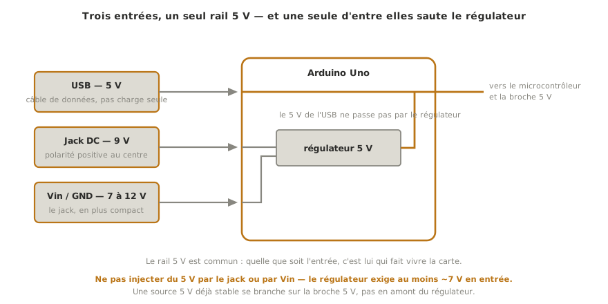
Powering an Arduino board means giving it the voltage and the current it needs to start, run its program, and feed the external components that depend on it. Three supply routes live side by side on an Uno: USB (from a computer or a charger), barrel jack (an external 7-12 V supply), Vin pin (the same as the jack, but as a pin). Choosing the right one — and sizing it — is the first thing to check when a project restarts on its own or refuses to start at all.
What is it for?
As long as a project sits on the breadboard, powered by the computer over USB, all is well. As soon as you add motors, relays, wireless modules or a TFT display, the current climbs, and the Arduino’s USB supply (500 mA shared on a computer) reaches its limits. Knowing the three supply routes and their constraints lets you:
- Choose the power supply (PSU) that fits the total consumption you expect (logic plus actuators plus accessories).
- Separate the supplies when the actuators disturb the logic (motors).
- Anticipate the consumption peaks (Wi-Fi transmitting, a motor starting, a relay pulling in).
Step by step
Four steps: choose the route, estimate the current, wire it, check that it holds.
1. Choose the supply route
| Route | Input voltage | Regulator | Typical limit | Use case |
|---|---|---|---|---|
| USB (type B port on the Uno R3, USB-C on the Uno R4) | 5 V (from a computer or a charger) | none (straight through) | 500 mA from a computer, up to 1-2 A from a USB-C charger | Programming and testing, projects with no actuators |
| Barrel jack | 7-12 V (Uno R3, max ~20 V); 6-24 V (Uno R4) | NCP1117 LDO (Uno R3) or ISL854102 switching converter (Uno R4) | ~800 mA out at 5 V in theory, ~500 mA in practice | Mobile projects, demonstrating without a computer |
| Vin pin | 7-12 V (same constraints as the jack) | same | ~500-800 mA | Power through a terminal block or a breadboard, functionally the same as the jack |
| 5 V pin (as an input) | regulated 5 V | none (bypasses the regulator) | depends on the external PSU | A stable external 5 V supply, no headroom |
| 3.3 V pin (as an input) | regulated 3.3 V | none (bypass) | rarely used as an input, ~150 mA as an output | Fine compatibility work, best avoided as an input |
Rule of thumb: USB for as long as it is enough, barrel jack when you need to run untethered or want more current.
2. Estimate the total current
Add the consumptions up:
- Arduino Uno R3 on its own: ~50 mA (with the board LED lit).
- Simple sensors (DHT11, HC-SR04): 1-15 mA each.
- SG90 servo at rest: 10 mA, moving: 100-200 mA, stalled: up to 500 mA.
- 5 V relay module: 70-80 mA when the relay pulls in.
- Standard DC motor: 100 mA to several amps depending on its size.
- ESP-01 Wi-Fi transmitting: 250-300 mA at the peak.
- RGB LED strip (60 WS2812B LEDs at full white): 3-5 A — a dedicated supply is compulsory.
- 16×2 LCD display (with backlight): 20-50 mA.
- 0.96″ SSD1306 OLED display: ~20 mA.
Quick method: estimate high for every component and add them up. Compare with what the chosen route can give. Safety margin of 1.5×.
For the general sizing method (power budget, choice of source, margins), see designing a power supply.
3. Wire it
USB: a good cable (data, not charge-only). On the Uno R3, a type B USB port; on the Uno R4, USB-C; on the Nano, mini-USB.
Barrel jack: a 9 V DC mains adapter, centre-positive polarity (the Arduino standard). The 0.5 A or 1 A printed on the adapter is its maximum capacity.
Vin pin: powering through this pin is the same as the barrel jack, in less space. Always tie GND as well.
External 5 V: if you already have a stable 5 V supply (the 5 V bus of the installation), power the board straight through the 5V pin. Do not feed 5 V through the jack or Vin: the board’s regulator (an NCP1117 on the Uno R3) needs at least ~7 V at its input to produce a stable 5 V.
4. Check that it holds
Once powered, measure with the multimeter:
- Voltage between 5 V and GND on the Arduino: must be ~5.0 V (4.8-5.2 V acceptable).
- Voltage between 3.3 V and GND: must be 3.3 V (3.2-3.4 V).
- Under load (with an actuator running): the 5 V must not sag below 4.5 V, or the microcontroller may reset.
Typical symptom of a weak supply: the Arduino reboots every time an actuator switches on. The current peak pulls the voltage below the microcontroller’s operating threshold, it resets (brown-out), then starts again.
Example — A battery-powered project: Arduino plus three modules
Typical case: powering an Arduino Uno with a DHT11 module, an SSD1306 OLED module and an SG90 servo, from a 7.4 V LiPo battery, for a mobile demonstration.
Estimate:
- Arduino: 50 mA
- DHT11: 2.5 mA
- OLED: 20 mA
- Servo moving: 200 mA at the peak
- Total: ~270 mA at the peak
Choice: power through the barrel jack from the 7.4 V battery, using a male jack connector. A 1000 mAh LiPo battery gives about 3 h of running time at the estimated draw.
Wiring:
- 7.4 V battery → barrel jack on the Arduino.
- DHT11 and OLED: powered from the Arduino’s regulated
+5 V(≤ 30 mA each, fine). - Servo: powered from the regulated
+5 V… or from a separate supply if the voltage is seen to sag.
#include <Servo.h>      // driving the servo
Servo monServo;          // servo object

void setup() {
  monServo.attach(9);    // servo signal on pin D9
  Serial.begin(115200);
}

void loop() {
  // sweep 0° → 180°: it is this movement that creates the current demand
  for (int a = 0; a <= 180; a += 10) {
    monServo.write(a);   // target position (degrees)
    delay(100);          // gives the servo time to reach the position
  }
  // ... reading sensors, updating the OLED
}
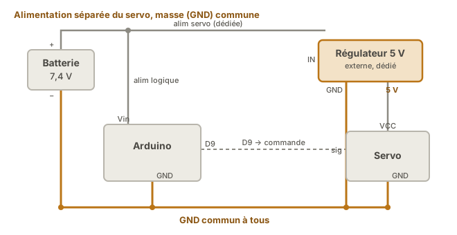
On the first run, the Arduino restarts every 5 seconds, right when the servo moves. The voltage on the regulated 5 V sags too far. Fix: power the servo straight from the 7.4 V battery through a dedicated external 5 V regulator, keeping GND common with the Arduino. Or slow the sweep down. See driving a servo for good practice on servo supplies.
Pitfalls
Feeding 5 V into Vin (or the jack). The board’s regulator needs more than 5 V at its input: on the Uno R3, the NCP1117 LDO drops about 1.2 V (aim for ~7 V minimum). On the Uno R4, the switching converter asks for at least 6 V. Feeding 5 V into Vin or the jack gives an under-regulated output (~3.8 V on the R3), and the Arduino turns unstable. To power it at 5 V, use the 5V pin directly (bypassing the regulator).
Feeding 12 V (or more) into the 5 V pin. Immediate destruction of the microcontroller (the supply goes straight onto the 5 V rail, and the regulator offers no protection). Three times the maximum it can take.
A 500 mA computer USB port for actuators. Symptom: the Arduino reboots when an actuator switches on. Diagnose that before hunting for a software bug. Fix: an external supply.
Barrel jack polarity reversed. The Arduino standard is positive at the centre, negative on the barrel. A 9 V adapter with reversed polarity will not start the Arduino (or worse, will damage the board if the reverse protection has been bypassed). Check the symbol on the adapter.
Wi-Fi transmission peak not anticipated. An ESP-01 or any Wi-Fi module draws short peaks (1-10 ms) of 300 mA while transmitting, invisible on a multimeter. A 470 µF to 1000 µF decoupling capacitor close to the module absorbs the peak and steadies the supply. See the ESP-01 notes.
No common GND between the Arduino and an external load. With two supplies (one for the Arduino, one for the motors), GND must be common. Otherwise the logic signals have no shared reference, the system does not work, and currents can flow where they should not. The diagram in the example above shows that common GND.
The Uno R3 regulator running hot. The linear regulator (the NCP1117, an LDO) dissipates (Vin − 5 V) × I_total. At 12 V in and 500 mA out: (12-5) × 0.5 = 3.5 W, enough to get seriously hot without a heatsink. Symptom: a smell, heat you can feel. Bring the input voltage down to 7-9 V (smaller drop, lower dissipation) or feed regulated 5 V through the 5 V pin. (The Uno R4, whose regulator is a switching one, does not suffer from this.)
Special case — Battery power for standalone projects
Three routes, depending on the constraints:
- 9 V battery (PP3): 500-600 mAh, poorly suited to hungry projects (laughable running time). Acceptable for short demonstrations.
- A pack of AA cells in series (4× 1.5 V = 6 V, or 6× 1.5 V = 9 V): 1500-3000 mAh. Good cost against running time for a school project.
- 7.4 V LiPo battery (two cells in series): 1000-5000 mAh, but it calls for a dedicated charger and precautions (cell balancing, protection against over-discharge).
See deep sleep and deep sleep on Arduino to save power on battery when the idle periods are long.
Where it fits in the project
- Step 4 of the concept phase — the technical state of the art and the arbitration between architectures take the supply in as a criterion (USB against standalone, a demonstration on mains against a mobile one).
- Step 2 of the proof of concept phase — as soon as you add the first power actuator, estimate the consumption and resize the supply if you need to.
- Step 4 of the technical design file phase — the demonstrator’s final supply (with its safety margin) is part of the BOM (the parts list).
- Step 2 of the integration and testing phase — checking that the 5 V holds under load on the integrated system (measured with the multimeter, watched on the oscilloscope).
Power is the most underrated part of a beginner’s project — ignored while everything works, blamed unfairly when some other bug turns up. Measuring it with a multimeter at the first suspicious symptom saves hours of wandering.
See also
- Arduino — hub of the Arduino tutorials
- Getting started with Arduino — where USB power is met for the first time
- Deep sleep on Arduino — cutting consumption for battery life
- Using a shield — the stacking that can double the total consumption
- Logic levels — for getting 3.3 and 5 V to live together
- Designing a power supply — the cross-cutting principles this page applies to the board
- Reading a datasheet — for finding a component’s nominal currents