A servo (short for servomotor) is a rotary actuator that moves to an angle command carried by a pulse-width-coded signal. On a standard servo (SG90, MG996R), the angle ranges from 0° to 180°. The Servo.h library shipped with the Arduino IDE wraps the signal generation: calling servo.write(angle) is all it takes to move.
What is it for?
The servo is the simplest actuator for producing controlled positional motion, where a DC motor only gives you speed and torque:
- Steering a mobile robot (steered wheel, rudder, tilting sensor mount).
- Sorting or diverting (a paddle that pushes a part one way or the other).
- Moving a simple articulated arm (a gripper that opens and closes, a short axis).
- Precision servomechanism (optical aiming, fine angular positioning with a metal-bearing MG996R).
Limit: a standard servo only turns through about 180°. For continuous rotation, look at continuous-rotation servos (which are driven by speed) or at DC motors.
Step by step
Four steps: choose the servo, wire it up, install Servo.h, write the code.
1. Choose the servo
| Part | Voltage | Torque | Range | Use |
|---|---|---|---|---|
| SG90 (plastic gears) | 4.8-6 V | ~1.8 kg·cm | 0-180° | Tests, light prototypes, educational robots |
| MG90S (metal gears) | 4.8-6 V | ~2.2 kg·cm | 0-180° | Grippers, repeated motion |
| MG996R | 4.8-7.2 V | 9-11 kg·cm | 0-180° | Arm joints, heavy grippers, loaded axes (high load) |
For a first test, the SG90 is the obvious standard — small, light, included in every kit.
2. Wire it up
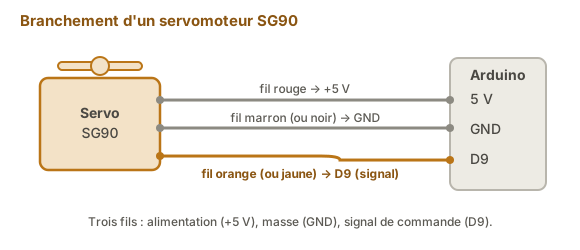
A servo has 3 wires:
| Colour | Signal |
|---|---|
| Red | +5 V |
| Brown (or black) | GND |
| Orange (or yellow, white) | 50 Hz PWM signal |
Minimal wiring (isolated test):
- Red →
+5 Von the Arduino - Brown →
GNDon the Arduino - Orange → pin D9 (PWM-capable, though
Servo.hdoes not use the hardware PWM, so any digital GPIO will do)
Wiring with a separate supply (recommended as soon as you have two or more servos, or a high-torque servo):
- Red →
+5 Vfrom a stable external supply (1-2 A) - Brown → ground shared with the Arduino (external supply and board)
- Orange → Arduino pin
3. Install Servo.h
Servo.h ships with the Arduino IDE: nothing to install.
#include <Servo.h>On ESP32 boards, the equivalent library is ESP32Servo (install it through the library manager: the native Servo.h does not work there).
4. Write the code
#include <Servo.h>

Servo monServo;

void setup() {
  monServo.attach(9);   // signal on D9
  monServo.write(90);   // initial position, mid-travel
  delay(1000);
}

void loop() {
  monServo.write(0);    // hard left
  delay(1000);
  monServo.write(90);   // middle
  delay(1000);
  monServo.write(180);  // hard right
  delay(1000);
}
Upload. The servo moves to three discrete positions, one second apart. If it twitches instead of going where you want, see the Pitfalls section.
Example — continuous sweep with speed control
A full case: a 0° → 180° → 0° sweep, with the speed set by a potentiometer.
Wiring: servo on D9 (as in the step 2 diagram), a 10 kΩ potentiometer on A0 (wired as a divider: see reading an analog sensor).
#include <Servo.h>

Servo monServo;
const int POT = A0;

int angle = 0;
int sens = +1;  // +1 or -1

void setup() {
  monServo.attach(9);
  monServo.write(angle);
}

void loop() {
  // Read the potentiometer to set the step size (speed)
  int valPot = analogRead(POT);
  int pas = map(valPot, 0, 1023, 1, 10);  // 1° to 10° per step

  angle += sens * pas;                            // advance one step in the current direction

  if (angle >= 180) { angle = 180; sens = -1; }   // upper limit: sweep back down
  if (angle <= 0)   { angle = 0;   sens = +1; }   // lower limit: sweep back up

  monServo.write(angle);
  delay(20);  // ~50 Hz refresh
}
How to read this code
The back-and-forth sweep rests on a
sensvariable holding+1(climbing towards 180°) or-1(descending towards 0°). On every pass throughloop(),sens * pasis added to the angle. When a limit is reached,sensis inverted and the servo heads back the other way. Themap(valPot, 0, 1023, 1, 10)turns the potentiometer position (0-1023) into a step of 1° to 10°: the larger the step, the faster the sweep.
Turn the potentiometer: the sweep speed changes. Handy for tuning the speed during a demo without recompiling.
Pitfalls
The Arduino reboots when the servo starts. The classic symptom: the servo’s current draw while moving (a few hundred mA for an SG90, over 1 A when an MG996R stalls) drags the +5 V rail down and the Arduino resets. Fix: a separate supply for the servo, with the ground shared with the Arduino.
No shared ground. Servo powered from a separate battery, ground wire not tied back to the Arduino: the PWM signal has no reference, and the servo either sits at a random position or does not move at all. Always share the ground as soon as there are two supplies.
The servo twitches (jitter). Several possible causes:
- Not enough current (see above).
- Signal wires too long or too noisy — shorten them, shield them.
- A timer clash with another library. On the Uno R3,
Servo.huses Timer1 and disables PWM on D9 and D10. Other libraries that use Timer1 (TimerOne,Wireon some forks) will clash.
write() range inverted or clipped. Some cheap servos do not cover exactly 0-180°. If you command 0° and the servo hits a mechanical hard stop, the current climbs and the servo heats up. Clamp the commanded range to 10°-170° to protect it.
Confusing write(angle) with writeMicroseconds(N). write(angle) takes 0-180° and converts internally. writeMicroseconds(N) takes the pulse width directly in µs (typically 1000-2000 µs, sometimes extended to 500-2500). On a servo that will not reach the expected extremes, writeMicroseconds() lets you calibrate finely.
Servo.h disabling PWM on D9/D10. Including Servo.h stops analogWrite(9) and analogWrite(10) from working: Timer1 is taken over. If you need PWM on those pins, either move to other pins or use an alternative library.
Too many servos on an Uno R3. Servo.h supports up to 12 servos on an Uno (a software limit), but the combined current draw quickly exceeds what the board’s 5 V regulator can deliver. Beyond two servos, an external supply is mandatory; beyond six, consider a dedicated driver (PCA9685, 16 PWM channels over I2C).
A servo that screams then heats up while standing still. The servo is trying to reach a position that is mechanically blocked. It draws full current without moving. Symptom: buzzing, heat. Diagnosis: the command is outside the servo’s mechanical range (badly calibrated), or the obstruction comes from outside. Detaching the servo (servo.detach()) cuts the signal and leaves it passive.
Special case — continuous-rotation servos
A continuous-rotation servo (sometimes labelled FS90R, MG995-360, or modified from a standard one) does not move to an angle: it turns one way or the other at a speed proportional to the command. The usual convention:
write(90)→ stopwrite(0)→ full speed one waywrite(180)→ full speed the other way
Very useful for light wheeled robots, replacing a DC motor plus H-bridge. Limits: no position feedback, poorly calibrated speed, best avoided for precise closed-loop control.
Position-feedback servos
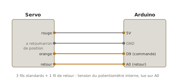
A standard servo commands a position but never tells you whether it actually got there: write(90) sends the command with no guarantee that the shaft sits at 90° (mechanical hard stop, overload, external blockage). A position-feedback servo answers that need by exposing a 4th wire reporting the measured angle, which is valuable on a 3-axis arm if you want to know where the joints really are and not just where you told them to go.
Worth remembering: every analog servo already works in closed loop, thanks to an internal potentiometer fixed to the shaft (that is what lets the servo “hold” its position). A feedback servo simply brings that signal out to an Arduino pin.
Reading the position (analog feedback)
The case that lives up to its name is the analog-feedback servo (the Adafruit Analog Feedback Servo, for instance): the 4th wire gives you the wiper voltage of the internal potentiometer directly, which is an image of the angle. You read it on an analog input (→ ADC).
#include <Servo.h>

Servo monServo;
const int CMD    = 9;    // servo command wire (PWM)
const int RETOUR = A0;   // 4th wire: internal potentiometer voltage

// ADC values recorded during calibration (measure them for EACH servo)
const int ADC_0   = 110;   // analogRead with the servo at 0 deg
const int ADC_180 = 910;   // analogRead with the servo at 180 deg

void setup() {
  Serial.begin(115200);
  monServo.attach(CMD);
}

void loop() {
  monServo.write(90);                  // command: go to 90 deg
  delay(500);

  int brut = analogRead(RETOUR);       // wiper voltage (0-1023)
  int angleReel = map(brut, ADC_0, ADC_180, 0, 180);  // converted to degrees

  Serial.print("Command 90 -> measured ");
  Serial.print(angleReel);
  Serial.println(" deg");
  delay(500);
}
How to read this code
The command (
write) and the measurement (analogRead) are two independent things: one tells the servo where to go, the other reads where it really is. TheADC_0andADC_180values cannot be guessed. They are calibrated: command the servo to 0° then to 180°, note theanalogReadvalue at each end, andmap()interpolates between the two. Every servo has its own bounds (the potentiometer is never perfectly centred), hence a calibration per unit.
What is it for?
- Confirming arrival — comparing command and measurement catches a servo that misses its target (obstruction, overload):
if (abs(angleReel - 90) > 5) { /* flag the deviation */ }. - A higher-level loop — controlling motion against the actual position rather than the assumed command.
- 3-axis arm — knowing the effective angle of each joint, to check a pose or log a movement.
Variant — digital feedback (PWM)
Some feedback servos use no potentiometer but a Hall-effect sensor, and report position as a PWM signal (duty cycle proportional to the angle) rather than a voltage. The Parallax Feedback 360° is the common example: feedback at 910 Hz, duty cycle from 2.7% to 97.1% over a full turn. You read it with pulseIn() (or an interrupt), not with analogRead. In exchange, a Hall sensor does not wear out and does not drift the way a potentiometer does. Check the model’s datasheet before wiring: analog feedback (→ analogRead on an A* pin) or PWM feedback (→ pulseIn on a digital pin).
Feedback is not metrology
Potentiometer feedback drifts (track wear, temperature): it is fine for indicative control (“has the arm roughly arrived?”), not for a precision measurement. For fine, lasting positioning, closed-loop control on a dedicated sensor is preferable (see PID tuning).
Where it fits in the project
- Step 2 of the proof-of-concept phase — first attempt at angular positioning on an isolated bench.
- Step 3 of the proof-of-concept phase — integrating the servo into the measure → decide → move chain (a presence sensor opening a hatch, for instance).
- Step 4 of the concept phase — the trade-off between standard servo, continuous-rotation servo, DC motor plus H-bridge and stepper motor is usually made while compiling the technical state of the art.
A properly wired servo (separate supply plus shared ground) is the most predictable actuator to bring into a school project: the same command gives the same result, to within its accuracy. That is what makes it the ideal tool for early demonstrations.
See also
- Arduino — hub for the Arduino tutorials
- Using a library — prerequisite,
Servo.hships with the IDE - Driving a PWM output — to understand the underlying signal
- Driving a DC motor — for controlled continuous rotation
- Driving a stepper motor — for precise multi-turn positioning
- Powering an Arduino board — for sizing the supply with servos
- Potentiometer — the internal sensor a position-feedback servo brings out
- Analog-to-digital converter — to read the analog feedback voltage
- PID tuning — for fine closed-loop positioning