A stepper motor turns in discrete angular steps — typically 200 steps per turn (1.8° per step) — under the sequenced drive of several coils. The rotor position is therefore known by construction without any feedback sensor, which makes the stepper the actuator of choice for precise multi-turn positioning (3D printers, CNC machines, scanners). This page covers two emblematic drivers: 28BYJ-48 + ULN2003 for the teaching version, and NEMA17 + A4988 for the industrial stepper.
What is it for?
Typical cases:
- Precise angular positioning (without a sensor, starting from a known home).
- Linear motion through a leadscrew — 3D printer axes, CNC, plotter, telescope.
- Very slow rotation without judder (where a DC motor would stutter).
- Multi-turn motorised valves, winches, clock mechanisms.
A quick comparison:
| Actuator | Position | Torque | Accuracy |
|---|---|---|---|
| Standard servo | 0-180° | low | medium |
| DC motor | none | good | none (without an encoder) |
| Stepper motor | by steps | medium | excellent |
Step by step
Four steps: choose the motor and driver pair, wire it up, install the library, write the code.
1. Choose the motor and the driver
Teaching version: 28BYJ-48 + ULN2003
- Motor: 28BYJ-48, 5 V, 4 wires plus one common (unipolar mode), 1:64 gearbox built in (so 2048 or 4096 steps per turn at the output shaft).
- Driver: ULN2003 (Darlington transistors), on a board with 4 LEDs that blink in coil order — very instructive.
- Included in most Arduino kits.
Industrial version: NEMA17 + A4988 or DRV8825
- Motor: NEMA17, bipolar, 4 wires, 200 steps/turn, 0.8 to 1.7 A per coil.
- Driver: A4988 or DRV8825, microstepping down to 1/16 or 1/32, controlled through just 2 pins (STEP, DIR).
- Used in 3D printers and CNC machines.
For a first teaching attempt, the 28BYJ-48 with a ULN2003 is unbeatable. For a serious project with real power, move to a NEMA17 with an A4988.
2. Wire it up
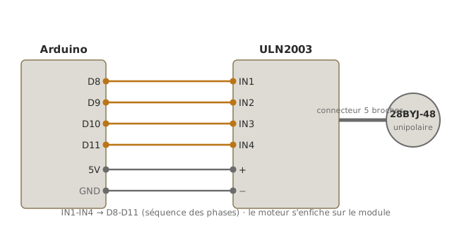
For a 28BYJ-48 with a ULN2003: the motor has a 5-pin Dupont connector that plugs straight onto the ULN2003 module. On the Arduino side:
| ULN2003 | Arduino Uno |
|---|---|
| IN1 | D8 |
| IN2 | D9 |
| IN3 | D10 |
| IN4 | D11 |
+ (supply) | +5 V (or an external 5-12 V supply) |
− (GND) | GND |
For a NEMA17 with an A4988:
| A4988 | Arduino Uno |
|---|---|
STEP | D2 |
DIR | D3 |
SLEEP ↔ RESET | tied together (to enable the driver) |
ENABLE | GND (always active) or an Arduino pin for enabling |
VDD (logic) | +5 V on the Arduino |
GND (logic) | Arduino GND |
VMOT (power) | external 12-24 V supply |
GND (power) | supply ground + Arduino ground (shared) |
1A, 1B, 2A, 2B | the motor’s 4 wires (2 per coil) |
Important on the A4988: a 100 µF capacitor between VMOT and GND is mandatory to absorb current spikes. Without it the driver is destroyed.
3. Install the library
Two options:
Stepper.h— ships with the IDE, simple, enough for a 28BYJ-48 with a ULN2003.AccelStepper— installed through the library manager, handles acceleration and deceleration ramps and coordinated multi-stepper motion. Essential as soon as you want smooth movement, or run two or more synchronised motors (CNC).
For a first attempt, Stepper.h is enough.
4. Write the code (28BYJ-48 + Stepper.h)
#include <Stepper.h>

const int PAS_PAR_TOUR = 2048;  // 28BYJ-48 with its 1:64 gearbox
Stepper monMoteur(PAS_PAR_TOUR, 8, 10, 9, 11);  // pin order IN1, IN3, IN2, IN4

void setup() {
  monMoteur.setSpeed(10);  // 10 rpm
  Serial.begin(115200);
}

void loop() {
  Serial.println("Clockwise");
  monMoteur.step(PAS_PAR_TOUR);  // one full turn
  delay(1000);

  Serial.println("Anticlockwise");
  monMoteur.step(-PAS_PAR_TOUR); // one turn the other way
  delay(1000);
}
Upload. The motor turns one full turn, pauses, then goes back the other way. The pin order (8, 10, 9, 11) matches the coil sequence: do not shuffle it at random, or the motor will vibrate without turning.
Example — motion driven by a step button
A full case: a button advances the motor by a quarter turn on each press.
Wiring: 28BYJ-48 and ULN2003 as in the step 2 diagram, plus a button between D2 and GND (INPUT_PULLUP, no external resistor).
#include <Stepper.h>

const int PAS_PAR_TOUR = 2048;
const int PAS_INCREMENT = PAS_PAR_TOUR / 4;  // quarter turn
Stepper monMoteur(PAS_PAR_TOUR, 8, 10, 9, 11);

const int BOUTON = 2;
bool dernierEtat = HIGH, etatStable = HIGH;
unsigned long dernierAntirebond = 0;

void setup() {
  monMoteur.setSpeed(15);
  pinMode(BOUTON, INPUT_PULLUP);
}

void loop() {
  bool lect = digitalRead(BOUTON);
  if (lect != dernierEtat) {
    dernierAntirebond = millis();
    dernierEtat = lect;
  }
  if (millis() - dernierAntirebond > 30 && lect != etatStable) {
    etatStable = lect;
    if (etatStable == LOW) monMoteur.step(PAS_INCREMENT);  // falling edge: one step per press
  }
}
How to read this code
Non-blocking debouncing follows the same pattern as for the DC motor:
dernierEtatspots the moment the raw reading changes (and restarts the clock),etatStableholds the state confirmed after 30 ms. The step is only triggered on a falling edge (INPUT_PULLUP→ pressed =LOW). Watch out:monMoteur.step()is blocking. During the quarter turn,loop()is frozen and the button is not read, so a press made while the motor moves is lost (see Pitfalls). To stay responsive, you need a non-blocking library such asAccelStepper.
Each press advances a quarter turn. Handy for sequential positioning projects (a dispenser, a multi-position selector).
Pitfalls
Wrong coil order. With Stepper(steps, A, B, C, D), the order of the 4 pins sets the coil sequencing direction. Get it wrong and the motor vibrates without turning. Fix: try the usual permutations, or check the driver’s datasheet (for a ULN2003 with a 28BYJ-48, (8, 10, 9, 11) is the standard order).
Not enough supply current. A 28BYJ-48 peaks at about 200-300 mA, a NEMA17 at 1-1.7 A per coil. Powering either from the Arduino’s +5 V restarts the board. Always give the motor its own supply (at the very least for a NEMA17), with a shared ground.
An A4988 with no capacitor on VMOT. The driver is destroyed almost immediately at switch-on by the inductive voltage spike. 100 µF minimum between VMOT and GND, close to the driver.
Wrong A4988 current setting. The driver’s potentiometer sets the current limit per coil. Too low → not enough torque, lost steps. Too high → driver and motor overheat. Calibrate it by measuring Vref with a multimeter, following the formula on the driver’s datasheet (Vref = 8 × R_SENSE × I_MAX, typically Vref ≈ 0.8 V for 1 A on an A4988 with R = 0.1 Ω).
Lost steps under load. Ask it to move too fast, or load it too heavily, and the motor skips steps: the position the program has computed no longer matches the real one. Symptom: a drift that accumulates over time. A stepper’s torque falls as the step frequency rises, the coil inductance stopping the current from building up before the next step. So the first reflex is to slow down, and to build speed through an acceleration ramp rather than starting at full rate (AccelStepper). Only then go looking for torque: check the current setting (the pitfall above), pick a better-sized motor or driver, or unload the axis mechanically (reduction, counterweight, return spring). And if torque is still short once those levers are exhausted, the problem has stopped being electronic: working out the torque needed, the reduction ratio and the load inertia is not covered here, it belongs to mechanical engineering and to our colleagues’ courses.
Heat building up on the ULN2003. Under sustained load the ULN2003 module heats up (Darlington transistors, passive dissipation). The 28BYJ-48 has no free mode: it draws its ~150 mA continuously, even at standstill. To cut standstill dissipation, switch the supply with a MOSFET or use a driver with a sleep mode.
The Stepper.h library is blocking. monMoteur.step(N) is blocking: nothing else runs while the command is in progress. For smooth motion plus parallelism, move to AccelStepper (non-blocking, with .run() called from loop()).
A4988 direction depends on DIR at the moment of the STEP. Changing DIR during an active STEP can produce erratic steps. Good practice: leave DIR stable for at least 1 µs before STEP, which every serious library does.
Special case — microstepping and smoothing
The A4988 / DRV8825 / TMC2209 drivers support microstepping: instead of running a full physical step, they interpolate the coil drive to produce intermediate positions (1/2, 1/4, 1/8, 1/16, 1/32 of a step).
Upsides: noticeably smoother motion, less noise, better angular accuracy.
Downsides: reduced effective torque at the intermediate positions (the motor spends more of its time holding an unstable position). Finer microstepping therefore never makes up for lost steps under load, it makes them worse. And coordinating the driver to come back to whole steps calls for advanced libraries.
On modern 3D printers, TMC2209 drivers run 1/256 microstepping, near-silent.
Where it fits in the project
- Step 2 of the proof-of-concept phase — checking motor and driver in isolation: a full turn each way, top speed without losing steps.
- Step 3 of the proof-of-concept phase — integration into a precise motion chain (an X axis, a multi-position dispenser, and so on).
- Step 4 of the concept phase — the trade-off between stepper and the alternatives (servo, DC motor plus encoder) according to the accuracy, torque and budget needed.
The stepper is the typical actuator of school projects aiming at precise repeatable motion without feedback — a moderate learning curve, and spectacular results in a demo.
See also
- Arduino — hub for the Arduino tutorials
- Using a library — prerequisite,
Stepper.hships with the IDE - Driving a DC motor — the continuous alternative
- Driving a servo — the 0-180° angular alternative
- Powering an Arduino board — sizing the supply with a power motor
- Interrupts — for reading a limit switch while the motor moves
- Energy chain — where the actuator sits between source and load
- Mechanical engineering — mechanical sizing, reduction, joints (interface towards our colleagues’ courses)