A DC motor is the reference actuator for producing continuous rotary motion with variable speed and direction. Unlike the servo, which moves to an angle, a DC motor turns continuously: its speed is set by PWM, its direction by reversing the polarity across its terminals. Reversing polarity from a microcontroller means going through an H-bridge (an L298N, TB6612FNG or DRV8833 driver). That circuit is what this page is about.
What is it for?
Typical uses in a school project:
- Two-wheel differential mobile robot (2 DC motors, independent speed and direction).
- Conveyor, winch, rotating arm — anything that calls for continuous rotation.
- Pump or fan system with speed control.
A quick comparison with the other actuators:
| Actuator | Position | Speed | Torque | Angular accuracy |
|---|---|---|---|---|
| Standard servo | ✅ 0-180° | poor | low | medium |
| DC motor + H-bridge | ❌ | ✅ continuous | good | none without an encoder |
| Stepper motor | ✅ by steps | ✅ controlled | medium | excellent |
Step by step
Four steps: choose the driver, wire it up, power it, write the code.
1. Choose the driver
| Driver | Motor voltage | Continuous current | Notes |
|---|---|---|---|
| L298N (classic module) | 5-35 V | 2 A per channel (with a heatsink) | The most widespread, high heat dissipation |
| TB6612FNG | 4.5-13.5 V | 1.2 A per channel (3.2 A peak) | MOSFET, little voltage drop, efficient |
| DRV8833 | 2.7-10.8 V | 1.2 A per channel | Compact, dual H-bridge on board |
| L9110S | 2.5-12 V | 0.8 A per channel | Small, compact, two motors |
For a first project: the L298N is the standard teaching module. For a serious project or a light robot, the TB6612FNG offers far better energy efficiency.
2. Wire it up
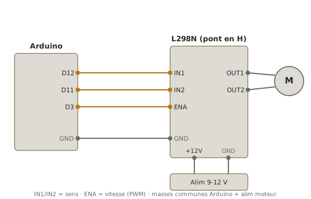
For an L298N driving one DC motor (same pins as in the Using a shield page for the motor shield):
| L298N pin | Connection |
|---|---|
IN1 | Arduino pin D12 (direction 1) |
IN2 | Arduino pin D11 (direction 2) |
ENA | Arduino pin D3 (PWM, speed) |
OUT1 | motor + terminal |
OUT2 | motor − terminal |
+12V (motor supply) | external 9-12 V supply |
GND (motor supply) | external supply ground + Arduino ground (shared) |
+5V (logic supply) | regulated internally by the L298N, can power the Arduino through the module’s 5 V rail |
H-bridge — L298N truth table:
IN1 | IN2 | ENA (PWM) | Behaviour |
|---|---|---|---|
| HIGH | LOW | > 0 | Forward at the PWM speed |
| LOW | HIGH | > 0 | Reverse at the PWM speed |
| LOW | LOW | × | Coasting |
| HIGH | HIGH | × | Active braking |
| × | × | 0 | Coasting (whatever IN1/IN2 are) |
3. Power it
A separate motor supply is mandatory as soon as the motor draws more than about 50 mA. Otherwise the Arduino’s regulator sags and the board reboots. Typical sources:
- 9 V battery or AA battery pack (6×1.5 V = 9 V) — short demos, ~50-100 mAh available.
- 2-cell LiPo battery (7.4 V nominal, 5000 mAh) — solid standalone projects.
- 9 V / 2 A bench supply — a stable test bench.
Ground shared between the Arduino and the motor supply: without it the logic signals have no reference.
4. Write the code
const int IN1 = 12;
const int IN2 = 11;
const int ENA = 3;  // PWM ~

void avancer(int vitesse) {  // 0-255
  digitalWrite(IN1, HIGH);
  digitalWrite(IN2, LOW);
  analogWrite(ENA, vitesse);
}

void reculer(int vitesse) {
  digitalWrite(IN1, LOW);
  digitalWrite(IN2, HIGH);
  analogWrite(ENA, vitesse);
}

void arret() {
  digitalWrite(IN1, LOW);
  digitalWrite(IN2, LOW);
  analogWrite(ENA, 0);
}

void setup() {
  pinMode(IN1, OUTPUT);
  pinMode(IN2, OUTPUT);
  pinMode(ENA, OUTPUT);
}

void loop() {
  avancer(150);
  delay(2000);
  arret();
  delay(500);
  reculer(200);
  delay(2000);
  arret();
  delay(500);
}
Upload. The motor turns for 2 s one way at moderate speed, stops for 500 ms, sets off the other way faster, and so on.
Example — motor control with a potentiometer and a direction button
A full case: a potentiometer sets the speed, a button reverses the direction on each press.
Wiring: the L298N as in the step 2 diagram; a 10 kΩ potentiometer on A0 (as a divider, see reading an analog sensor); a button between D2 and GND (INPUT_PULLUP, no external resistor).
const int IN1 = 12, IN2 = 11, ENA = 3;
const int POT = A0;
const int BOUTON = 2;

bool sensAvant = true;
bool dernierBouton = HIGH, etatStable = HIGH;
unsigned long dernierAntirebond = 0;
const unsigned long DELAI_REBOND = 30;

void setup() {
  pinMode(IN1, OUTPUT); pinMode(IN2, OUTPUT); pinMode(ENA, OUTPUT);
  pinMode(BOUTON, INPUT_PULLUP);
}

void loop() {
  // Speed from the potentiometer
  int vitesse = map(analogRead(POT), 0, 1023, 0, 255);

  // Button with debouncing
  bool lect = digitalRead(BOUTON);
  if (lect != dernierBouton) {
    dernierAntirebond = millis();
    dernierBouton = lect;
  }
  if (millis() - dernierAntirebond > DELAI_REBOND && lect != etatStable) {
    etatStable = lect;
    if (etatStable == LOW) sensAvant = !sensAvant;  // falling edge: one flip per press
  }

  // Apply
  if (sensAvant) { digitalWrite(IN1, HIGH); digitalWrite(IN2, LOW); }
  else           { digitalWrite(IN1, LOW);  digitalWrite(IN2, HIGH); }
  analogWrite(ENA, vitesse);
}
How to read this code
Non-blocking debouncing rests on two variables:
dernierBoutonholds the last raw reading (to spot the moment the signal moves and restart the clock),etatStableholds the confirmed state (the one you keep once the signal has been stable forDELAI_REBOND). Direction only flips on a falling edge (etatStable == LOW): withINPUT_PULLUPthe pin sitsHIGHat rest and drops toLOWwhen pressed — one flip per press, with no spurious bounce. Everything is non-blocking: nodelay(), and the motor keeps being driven on every pass throughloop().
Turn the potentiometer, press the button: direction and speed change in real time.
Pitfalls
The Arduino reboots when the motor starts. Inrush current at switch-on, +5 V rail sagging. Fix: a separate supply for the motor, and a 100 µF capacitor close to the motor terminals.
No shared ground. IN1/IN2 signals with no reference: the H-bridge switches at random. Always share the ground.
IN1 and IN2 both HIGH. Active braking (an internal short across the bridge). Held too long, the bridge heats up: the L298N’s thermal protection may shut the output down. Use it only for deliberate, brief braking.
Reversing polarity instantly. Taking IN1/IN2 from HIGH/LOW to LOW/HIGH without passing through LOW/LOW causes a violent reverse current, a current spike that can destroy the driver. Good practice: arret() plus delay(50) before reversing.
Missing flyback diodes. L298N modules include protection diodes, bare drivers (discrete transistors) do not. Without them, the motor’s inductance generates destructive spikes every time the current is cut. Check the module’s datasheet.
Motor stall (rotor blocked). The motor draws full current (stall current is roughly 5-10× the rated current) without turning: it heats up fast. Detect it by measuring current or with a rotation sensor, and cut power.
Voltage drop across the L298N. The L298N drops about 2 V per output (bipolar technology). With 12 V into the motor side, only about 10 V is left at the motor terminals. For projects that care about efficiency, prefer the TB6612FNG (drop below 0.3 V).
PWM too slow, making the motor audible. On the Uno R3, analogWrite(D3) runs at about 490 Hz, perceptible as a whine. To drive it quietly, raise the PWM frequency (see hardware timers) or move to another pin (D5/D6 at 980 Hz).
Special case — a motor with an encoder for closed-loop control
A bare DC motor has no feedback at all. You ask it to turn at analogWrite(150), but its real speed depends on the supply voltage, on the mechanical load, on wear. For precise control:
- An incremental encoder (Hall, optical) on the motor shaft → counting turns through interrupts.
- A PID control loop on the measured speed → see PID control.
This is the natural next step for a DC-driven robot that needs a repeatable trajectory.
Where it fits in the project
- Step 2 of the proof-of-concept phase — checking motor and driver torque on an isolated bench (rotation, direction, usable speed range).
- Step 3 of the proof-of-concept phase — integration into the measure → decide → move chain.
- Step 4 of the concept phase — the trade-off between DC motor, stepper motor and servo, according to what the drive function needs.
A two-wheel mobile robot with an L298N and two DC motors is one of the most instructive school proofs of concept: it puts GPIO, PWM, separate supply and debouncing to work in a single project.
See also
- Arduino — hub for the Arduino tutorials
- Driving a PWM output — prerequisite (analogWrite, PWM frequency)
- Using a shield — a motor shield uses the very same L298N
- Driving a servo · Driving a stepper motor — alternatives
- Interrupts — to read an encoder in closed loop
- PID control — to control speed
- Reading a datasheet — to size driver and supply