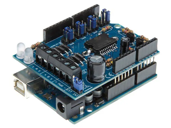
A shield is an expansion board that mounts on top of the Arduino by stacking (piggyback), reproducing the form factor of the host board and its layout of female headers. Where a module is wired up with jumper leads, a shield clips on — no wiring, no breadboard. That mechanical integration comes at a price: a shield is dedicated to one function (motor shield, ethernet shield, data logging shield, proto shield) and claims a precise set of pins that you need to know about to avoid conflicts.
What is it for?
The shield is the quickest way to add a substantial function to an Arduino with no wiring study: driving motors (motor shield), Ethernet (ethernet shield), GSM (GSM shield), touch TFT display (TFT shield), solderable prototyping (proto shield). Three complementary roles:
- Saving time — a motor shield fitted plus its library, and you are driving two motors in five minutes.
- Mechanical robustness — a rigid stack, no cables to work loose.
- Standardisation — the shield ecosystem follows the Uno form factor, so a great many are compatible across boards (Uno R3, R4, Mega).
Limit: a shield takes its pins exclusively. Worth knowing before you stack a second one.
Step by step
Four steps: identify the shield’s pinout, stack it, power it, install its library.
1. Identify the shield’s pinout
Every Uno-compatible shield uses the pins in the area it occupies. To find out which ones:
- Official documentation of the shield (Adafruit, Arduino) — always there, to be read before you use it and before you wire anything else.
- The shield’s silkscreen — the pins used are marked on the PCB.
- Testing by unstacking — fit it, run it with its example, take it off, look at which pins were being used.
A few typical examples:
| Shield | Pins occupied | Notes |
|---|---|---|
| Official Arduino Motor Shield (L298P) | D3, D8, D9, D11, D12, D13 | PWM plus direction for 2 motors |
| W5500 ethernet shield | D10 (CS), D11-D13 (SPI), D4 (SD CS) | Shared SPI bus |
| Data logging shield | D10 (SD CS), D11-D13 (SPI), A4-A5 (RTC I2C) | SPI plus I2C |
| Proto shield | none | Blank area to solder onto |
2. Stack the shield onto the Arduino
The operation is mechanical: line the shield’s male pins up with the Arduino’s female headers, and press gently and evenly until the shield sits flat.
Points to watch:
- Line it up before pressing — a bent pin can go into the wrong hole. Check by eye.
- Never stack under power — unplug USB and any external supply before stacking or unstacking.
- Check the spacers — for heavy shields (an LCD with a heatsink, a motor shield with a cooler), plastic spacers between the host board and the shield prevent short circuits.
3. Power the whole thing
Three cases:
- Low-power shield (proto, ethernet, RTC) — the Arduino’s USB is enough.
- Shield drawing a moderate current (LCD with backlight, ethernet) — move to a 7-12 V barrel jack supply on the Arduino, or a good-quality USB supply (5 V / 2 A).
- Shield with power actuators (motor shield with DC motors, GSM with its transmission peak) — a separate supply for the load on the shield (jack input or terminal block), and USB or jack for the Arduino’s logic.
For a motor shield (L293D, L298P…): a motor supply terminal block lets you power the motors directly at 7-12 V, without going through the Arduino’s 5 V regulator. That is compulsory as soon as the motors draw more than 50 mA.
4. Install the shield’s library
Most shields have their own dedicated library. See using a library.
For a motor shield (the example used here), two main families: the shield built around the L293D (the most widespread, known as “v1”) is driven with the Adafruit Motor Shield library (version 1.x). The Adafruit Motor Shield V2 (a TB6612 driver, commanded over I2C by a dedicated PWM chip) uses the Adafruit Motor Shield V2 library. Install it through the manager, open an example shipped with the library, upload.
Example — Motor shield (L293D): running a DC motor
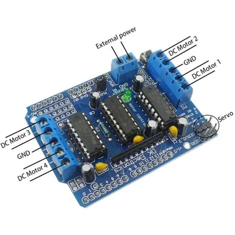
The motor shield built around the L293D (the most widespread, known as “v1”) stacks onto the Arduino and is driven entirely by its library: no pin wiring at all, which is the whole point of a shield.
Stacking: the shield straight onto the Arduino Uno.
Motor: a 6-9 V DC motor on the M1 terminal block (two wires).
Motor supply: a 9 V battery or a bench supply on the shield’s motor supply terminal block (separate from the USB powering the logic).
Library: Adafruit Motor Shield library (version 1.x, for L293D shields). Install it through the manager (see using a library).
Code:
#include <AFMotor.h>      // library of the L293D shield (Adafruit Motor Shield v1.x)

AF_DCMotor moteur(1);      // motor wired to the M1 terminal block (ports 1 to 4 available)

void setup() {
  moteur.setSpeed(150);    // speed from 0 to 255 (the shield handles the PWM signal)
}

void loop() {
  moteur.run(FORWARD);     // forwards
  delay(2000);
  moteur.run(RELEASE);     // free-wheeling: the motor coasts to a stop
  delay(1000);
  moteur.run(BACKWARD);    // backwards
  delay(2000);
  moteur.run(RELEASE);
  delay(1000);
}
You touch no pin directly: the library knows which pins the shield occupies. The detail of driving a DC motor (H-bridge, direction, speed) is covered by its own page (see driving a DC motor).
Pitfalls
Pin conflict between shields. Stacking an ethernet shield (SPI on D10-D13) and a motor shield that also uses D11/D12: conflict, and one of the two stops working. Read the notices before stacking.
SPI shared between devices. An ethernet shield plus a data logging shield stacked together share the SPI bus (D11-D13) but each has its own CS (SS) pin. Check that the two CS pins are different. Otherwise both devices answer at once and the communication is corrupted.
Under-powered shield. A computer’s USB gives at most 500 mA. An ethernet shield in use draws 150 mA, a motor shield draws 20 mA idle but up to 2 A under load. The Arduino reboots. Move to an external power supply as soon as a shield consumes anything.
Stacked the wrong way round. The shield’s orientation is set by the pin layout. It should not be possible to stack it backwards on an Uno (the headers are placed asymmetrically), but with some badly designed shields it is. Always check the orientation of the labels before pressing.
Shield pinout not Uno-compatible. A few shields assume a strict Uno layout (D0-D13, A0-A5). Stacked on a Mega, they fit but do not always land on the right pins (the SS / MOSI / MISO / SCK pins are on D50-D53 on the Mega, not on D10-D13). Read the compatibility notes.
Ageing library. The older L293D shields (“v1”) and their historic library can give trouble with recent IDEs (compilation failing). Prefer an up-to-date version of the library, or for a new project a V2 shield (TB6612, commanded over I2C).
Stacking live. Stacking or unstacking a shield on a powered Arduino can destroy pins through a transient short circuit. Always unplug USB first.
Special case — Proto shields and “do-it-yourself” shields
A proto shield is a blank shield (a soldering area with no functional tracks) used to build your own circuit in an Uno-compatible layout. It is the middle step between the breadboard (volatile) and a dedicated PCB (long to design and manufacture).
Handy for:
- Turning a validated breadboard build into a sturdier soldered version.
- Adding a few discrete components (resistors, capacitors, diagnostic LEDs) to a project.
- Learning surface-mount or through-hole soldering on a pre-drilled grid.
For a school project that has to show a final demonstrator that works and looks the part, a soldered proto shield is markedly more convincing than a breadboard.
Where it fits in the project
- Step 4 of the concept phase — the technical state of the art often takes the available shields in as PoC accelerators (“take a motor shield, save two weeks”).
- Step 2 of the proof of concept phase — stacking and testing the shield on its own, before integrating it into the whole system.
- Step 4 of the technical design file phase — deciding between “shield plus home-made proto shield” and “dedicated PCB” on robustness, cost and lead time.
A well-chosen shield early in a project buys PoC time and robustness on the final demonstrator. The other way round, piling up incompatible shields is a mechanical and electrical trap you pay for over the long run.
See also
- Arduino — hub of the Arduino tutorials
- Wiring a module — the unstacked alternative (jumper leads)
- Driving a DC motor — the typical use of a motor shield
- Powering the board — for sizing the PSU with a shield stacked
- Shield — the cross-cutting concept page