A module is a small prefabricated PCB carrying a main component (a sensor, a driver, a converter) surrounded by its minimal application circuit: supply, pull-ups, decoupling capacitors, a connector to work with. Modules save the designer all the low-level wiring of the datasheet: what remains is to plug in four jumper leads and call the library. This page covers the generic wiring of a module: identifying the pins, the supply, the signals, and the pitfalls that make a freshly delivered module refuse to start.
What is it for?
A typical school project carries 5 to 15 modules: a sensor module (DHT11, HC-SR04, BMP280, MPU6050), a driver module (L298N, DRV8833), a display module (I2C OLED, I2C LCD), a communication module (HC-05 Bluetooth, ESP-01 Wi-Fi), a power module (an LM2596 regulator, a USB converter), a utility module (DS3231 RTC, MicroSD). They all follow the same wiring logic: mastering it once saves hours of fumbling.
Step by step
Four steps: identify what the pins do, check the supply voltage, wire signals and ground, check the pull-ups.
1. Identify the module’s pins
A module carries a pinout silkscreened on the PCB or printed on the label. Four recurring families of pins:
- Supply:
VCC(orVIN, or+) andGND(or−). Always there, always in pairs. - Logic signals:
SCL/SDAfor I2C,SCK/MOSI/MISO/CSfor SPI,TX/RXfor UART, or plain GPIO pins (OUT,INT,Echo,Trig). - Configuration: physical straps, jumpers to remove to change an option (a pull-up resistor to take out, a 3.3 / 5 V supply to select).
- Power terminal block: on driver modules (L298N, contactor), a 5 V logic side plus a separate side for the load.
When the pinout is not obvious, look for the module’s documentation on the supplier’s site, or search for images of “module DHT11 pinout”.
2. Check the supply voltage it takes
This is the number one trap when you move from one Arduino board to an ESP32 or back. Three cases:
- 5 V only module (typically: older modules, entry-level HC-SR04 boards, 5 V relay modules) — do not power it at 3.3 V, or it will start erratically or not at all.
- 3.3 V only module (ESP-01, some MPU6050 variants) — do not power it at 5 V, or you destroy the regulator or the component.
- 3.3 V to 5 V module (most modern Adafruit and SparkFun modules, I2C modules with a built-in regulator) — tolerant, but read the silkscreen.
For wiring the logic signals between a 5 V board (Uno R3) and a 3.3 V only module: see logic levels. Shifting is compulsory in that direction.
3. Wire signals and ground
The inviolable rule: the module’s ground (GND) must be tied to the Arduino’s ground, even when the supply is separate. With no common GND the signals have no reference and the module does not answer (or answers at random).
For the rest: follow the logic of the bus in use (see communication buses). A few common rules:
- Consistent colours: red for
VCC, black forGND, other colours for signals. A discipline that saves time when debugging. - Short jumper leads: under 20 cm for fast digital signals (I2C, SPI), to keep out noise and reflections.
- Solid connectors: a badly seated jumper lead is a cause of intermittent symptoms. Tug on it to check, or solder the module onto a breadboard for lasting projects.
4. Check the pull-ups and the configuration
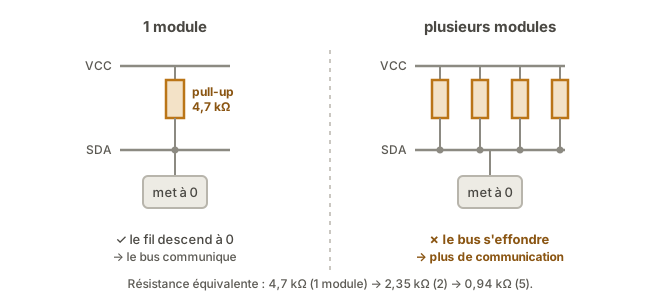
A great many I2C modules carry their own pull-up resistor on SDA / SCL (often 4.7 kΩ). On an I2C bus, those two wires are shared by every module and held high by that pull-up resistor, which pulls the wire up. To send a 0, a component has to pull the wire down against that resistor.
With a single module, all is well. But plugging several onto the same bus amounts to putting all those pull-up resistors in parallel: if too many modules are connected to the I2C bus, the sheer number of resistors in parallel makes the bus collapse and it can no longer be used to communicate.
Typical symptom: one module works on its own, but two modules together stop answering. Fix: keep one single pull-up active. Remove the little pull-up jumper (or cut the track provided) on every module but one.
The other jumpers to check. A great many modules also carry small configuration links:
- I2C address (PCF8574, I2C LCD) — often three bridges to choose one address out of eight, to be adjusted if two modules share the same one.
- 3.3 / 5 V supply (some SD card modules).
- Relay or opto enable (relay modules).
A module that “seems dead” often just has a jumper in the wrong place: inspect it before believing it faulty.
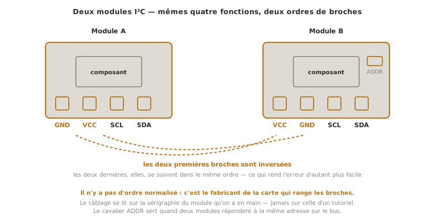
There is no standard pin order on I2C modules: two examples of the same part number, bought six months apart, can have VCC and GND swapped. Copying the wiring from a tutorial without re-reading the silkscreen of the module in your hand means putting 5 V onto the ground: the module does not recover from that.
Example — Wiring a DHT11 module (temperature plus humidity)
The full case on a module emblematic of Arduino kits.
DHT11 module:
- 3 typical pins:
+(VCC, 3.3-5 V),OUT(1-wire digital signal),−(GND). - Some modules have 4 pins: they add
NC(not connected). - A 10 kΩ pull-up resistor built in on
OUT(on the module versions, not on the bare component).
Wiring:
- module
+→ Arduino+5 V - module
−→ ArduinoGND - module
OUT→ Arduino pin D2
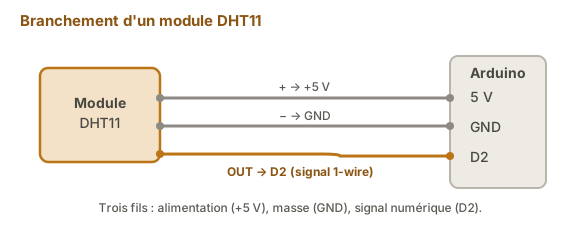
Library: DHT sensor library (by Adafruit). Install it through the manager (see using a library).
Code:
#include <DHT.h>           // DHT library (Adafruit): handles the sensor's 1-wire protocol

const int BROCHE_DHT = 2;       // the module's OUT wired to D2
const int TYPE_DHT = DHT11;     // sensor type (DHT11 here; DHT22 = another constant)

DHT dht(BROCHE_DHT, TYPE_DHT);  // create the sensor object

void setup() {
  Serial.begin(115200);    // serial link, to print the readings
  dht.begin();             // start the sensor
}

void loop() {
  delay(2000);             // the DHT11 takes 1 reading/s; 2 s stays cautious (and suits the DHT22)
  float h = dht.readHumidity();      // relative humidity (%)
  float t = dht.readTemperature();   // temperature (°C)

  if (isnan(h) || isnan(t)) {        // isnan = "is Not A Number": did the reading fail?
    Serial.println("Echec de lecture");
    return;                          // skip this pass, try again on the next
  }
  Serial.print("T="); Serial.print(t); Serial.print("°C\t");   // \t = tab
  Serial.print("H="); Serial.print(h); Serial.println("%");
}
Upload and watch the serial monitor. Breathe on the sensor: the humidity climbs quickly.
Pitfalls
Confusing VCC with the signal. Wiring the module’s OUT to the Arduino’s +5 V (instead of pin D2) releases no smoke, but the module does not answer. Check the wiring before every upload, methodically.
GND missing. A module powered on VCC but with GND not tied to the Arduino’s GND: the typical symptom is that the module seems powered (its LED lights) but no signal gets through. Always tie GND as soon as you connect VCC.
Powering a hungry module from an Arduino pin. An ESP-01 Wi-Fi module draws peaks of 300-400 mA while transmitting. The Arduino’s +5 V pin cannot take it: the Arduino reboots over and over. A stable external supply for hungry modules.
Incompatible logic levels. Wiring the 5 V output of an HC-SR04 to a 3.3 V input on an ESP32 damages the pin after a few minutes. Check the input tolerance (see logic levels).
Several I2C pull-ups in parallel. Two I2C modules on the same bus, each with its built-in 4.7 kΩ pull-up: an equivalent resistance of 2.35 kΩ. With 3 modules: 1.57 kΩ. With 5 modules: 940 Ω. Often too low, and the bus stops working. Disable the pull-ups on every module but one.
Configuration jumper in the wrong place. A module that seems dead may simply have its address jumper in the wrong position (clashing with another I2C device), or its VCC jumper on 3.3 V instead of 5 V. Inspect the module’s documentation to find every strap.
Counterfeit module. For the common consumer modules (DHT22, MPU6050) there are counterfeits that vaguely pass the first tests and then drift. Symptom: readings correct at first, slow degradation, or random failure. For a serious project, buy from a known source (Adafruit, SparkFun, Mouser).
Special case — A module with no datasheet
Generic unbranded modules, marked with a bare reference (HW-XXX, KY-XXX) with no identifiable supplier. Three routes:
- Look for the reference of the main component soldered onto the module (for instance
MAX30102, readable with a magnifier) — the component’s datasheet exists, and the module’s wiring follows from it. - Search for the module’s reference plus
pinoutin images (the Arduino community documents these modules heavily). - As a last resort, identify the pins with a multimeter: continuity with the main component’s
GND, a direct link to VCC, and so on.
See reading a datasheet for the identification method.
Where it fits in the project
- Step 2 of the proof of concept phase — every module of the project is validated on its own: supply, GND, signals, a first library example. Before integration.
- Step 2 of the integration and testing phase — every module is requalified inside the integrated system (multiple pull-ups, shared supply, bus clashes).
A module wired properly at the start of the PoC is a subsystem you will not have to revisit. Investing the time in validating it on its own stops hardware problems from polluting the commissioning of the software downstream.
See also
- Arduino — hub of the Arduino tutorials
- Using a shield — the alternative to a module (the stackable form)
- Using a library — to drive the module from software
- I2C on Arduino · SPI on Arduino · UART on Arduino — depending on the module’s bus
- Logic levels — for 3.3 / 5 V compatibility
- Reading a datasheet — to check voltage, current and signals