I2C (Inter-Integrated Circuit) is a synchronous serial bus on two wires — SDA (data) and SCL (clock) — that lets several devices live together on the same bus, each identified by a 7-bit address. Where UART is limited to point-to-point, I2C networks up to a theoretical 127 devices on those same two wires. It is the bus of choice for the more advanced sensors (BMP280, MPU6050, BME680, MAX30102), for displays (SSD1306 OLED, LCD through a PCF8574) and for clocks (DS3231, DS1307).
What is it for?
Three complementary roles on a school project:
- Multiplexing several sensors onto 2 pins (SDA plus SCL) — precious when GPIO pins are scarce.
- Connecting a display without tying up a large number of pins (an I2C SSD1306 OLED asks for only 2, against 16 for a parallel LCD).
- Reading from and writing to utility components: RTC, external EEPROM, GPIO expander (PCF8574, MCP23017).
The Arduino API goes through the Wire.h library, shipped with the IDE by default.
Step by step
Four steps: find the I2C pins, wire it with pull-ups, scan the addresses present, read a device.
1. Find the board’s I2C pins
| Board | SDA | SCL |
|---|---|---|
| Uno R3, Nano (ATmega328P) | A4 | A5 |
| Mega 2560 | D20 | D21 |
| Uno R4 | A4 (plus a dedicated SDA) | A5 (plus a dedicated SCL) |
| ESP32 | GPIO 21 (default) | GPIO 22 (default), reconfigurable |
On the Uno R3, the SDA/SCL pins are also duplicated at the top of the board (next to the AREF pin) on the more recent boards, functionally the same thing.
2. Wire it with pull-ups
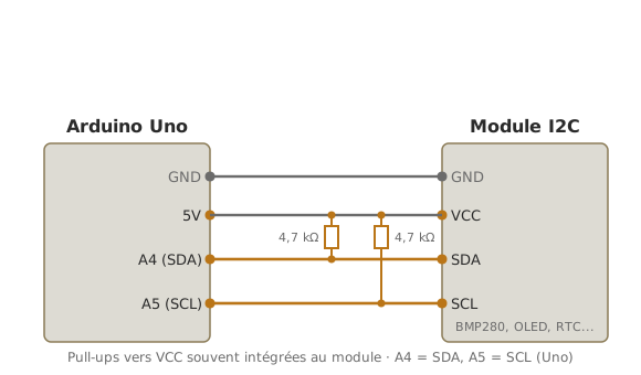
I2C needs pull-up resistors to VCC on SDA and SCL (typically 4.7 kΩ for 5 V, 2.2 kΩ for 3.3 V). Most commercial I2C modules include them: no need to add them by hand for a first try with a single module. Worth noting: no Uno board (R3 or R4) carries usable I2C pull-ups (on the R4, only solder pads are provided), so you rely on the module’s.
Generic wiring:
| Module | Arduino Uno |
|---|---|
| VCC | 5 V (or 3.3 V depending on the module) |
| GND | GND |
| SDA | A4 |
| SCL | A5 |
3. Scan the I2C addresses present
Before any application code, check that the module answers, with an I2C scanner, a sketch that tries every address from 1 to 127 and lists the ones that answer.
#include <Wire.h>

void setup() {
  Wire.begin();           // start the I2C bus (Arduino as the controller)
  Serial.begin(115200);
  delay(2000);            // leave time to open the serial monitor
  Serial.println("Scan I2C...");

  byte trouves = 0;
  for (byte adresse = 1; adresse < 127; adresse++) {   // try every possible address
    Wire.beginTransmission(adresse);      // prepare a message for this address
    byte erreur = Wire.endTransmission();  // send it: 0 = a device answered (ACK)
    if (erreur == 0) {
      Serial.print("Device a 0x");
      if (adresse < 16) Serial.print("0");  // padding: 0x7 -> 0x07 (two digits)
      Serial.println(adresse, HEX);         // address printed in hexadecimal
      trouves++;
    }
  }
  if (trouves == 0) Serial.println("Aucun device trouve.");
}

void loop() {}
How to read this code
The scanner uses a trick:
beginTransmission(adresse)prepares a message for one address, andendTransmission()actually sends it onto the bus. If a device carries that address, it answers with an ACK andendTransmission()returns0. Otherwise there is no answer and the code is non-zero. By sweeping addresses 1 to 126 you list everything that is wired up, without knowing anything about the devices in advance. Theif (adresse < 16) Serial.print("0")line is purely for display: it pads0x7out to0x07so the addresses line up on two digits.
Upload, open the serial monitor, read the address. If the scanner finds nothing: check the wiring (SDA/SCL not swapped, pull-ups, module supply).
Typical addresses: SSD1306 OLED = 0x3C or 0x3D; BMP280 = 0x76 or 0x77; DS3231 = 0x68; MPU6050 = 0x68 or 0x69; I2C LCD (through a PCF8574) = 0x27 or 0x3F.
4. Read a device with its library
Once the address is confirmed, install the component’s library (see using a library), open an example, adjust the address, upload. The reading is wrapped up by the library: no need to touch Wire.h directly in 99% of cases.
Example — Reading a BMP280 (pressure and temperature)
The full case on a module emblematic of school projects. (Wiring: one module on A4/A5, as in the diagram of step 2.)
Library: Adafruit BMP280 Library (library manager, type “BMP280”). It also installs Adafruit BusIO and Adafruit Unified Sensor as dependencies. Accept.
Code:
#include <Wire.h>
#include <Adafruit_BMP280.h>

Adafruit_BMP280 bmp;  // sensor on the I2C bus

void setup() {
  Serial.begin(115200);
  delay(2000);

  if (!bmp.begin(0x76)) {  // start the sensor at the address found by the scanner
    Serial.println("BMP280 introuvable, verifier le cablage");
    while (1);             // no sensor: block here (nothing to do without it)
  }
  Serial.println("BMP280 OK");
}

void loop() {
  // the library wraps up the I2C dialogue: you read values ready to use
  Serial.print("T = "); Serial.print(bmp.readTemperature()); Serial.print(" °C\t");
  Serial.print("P = "); Serial.print(bmp.readPressure() / 100.0); Serial.print(" hPa\t");
  Serial.print("Alt = "); Serial.print(bmp.readAltitude(1013.25)); Serial.println(" m");
  delay(1000);
}
Breathe on the module: the temperature rises. Change the altitude (walk up a flight of stairs): the pressure drops by about 12 Pa per metre, and the estimated altitude changes.
Pitfalls
Wrong address. A library’s default address (often 0x77) that does not match the module’s real address (often 0x76 on generic BMP280 boards): the device cannot be found. Always start with the scanner.
Pull-ups missing or too many. With no pull-up the bus floats and nothing works. With too many pull-up modules in parallel, the equivalent resistance gets too low and the bus can no longer hold the rising edge. Disable the pull-ups on every module but one (a jumper to unsolder).
Incompatible VCC level. A 3.3 V module powered at 5 V: destruction. A 5 V module on 3.3 V works badly or fails to start. Check the module’s documentation. For mixed 3.3 V / 5 V buses, use a two-way I2C level shifter (a PCA9306, or a BSS138 MOSFET circuit).
Address clash between devices. Two MPU6050 boards share the default address 0x68. Most modules let you move a strap or pull a pin to switch to 0x69. Read the module’s documentation. Without that, both devices answer at once and the bus is corrupted.
SDA/SCL swapped. The scanner finds nothing. Check that SDA really is on A4 and SCL on A5 (on the Uno).
Cables too long. I2C tolerates up to ~1-2 m of wiring in standard mode (100 kHz) with correctly sized pull-ups. Beyond that, or on noisy cables, the frames are corrupted. Shorten, screen, or move to a differential bus (CAN, RS-485).
Wire does not start on the ESP32. Wire.begin() with no arguments uses GPIO 21/22 by default on the ESP32. To reconfigure: Wire.begin(SDA, SCL) with the pins you want. On other boards (Wemos D1 Mini, NodeMCU), the default pinout differs.
Special case — Several I2C buses
On the ESP32 or the Uno R4 WiFi, you can bring up several independent I2C buses to resolve address clashes or spread the load:
- ESP32: two I2C controllers,
WireandWire1, on separate pins. - Uno R4 WiFi: the Qwiic connector exposes a 2nd I2C bus (
Wire1, 3.3 V), separate from the mainWirebus (A4/A5). - On the Uno R3, a software alternative:
SoftI2CMaster— an I2C bus emulated by bit-banging on any pair of pins.
For two devices at the same address on the same bus, a lighter alternative: use an I2C multiplexer such as the TCA9548A (8 channels), which presents one device per channel to the main bus.
Where it fits in the project
- Step 2 of the proof of concept phase — every I2C sensor or display is validated in two moves: the scanner to confirm the address, a library example to confirm the reading.
- Step 4 of the concept phase — the technical state of the art favours I2C as soon as you have 2 or more devices, or need to save GPIO pins.
The I2C scanner is the bus’s universal diagnostic tool, to be kept in a corner of your working environment and uploaded at every new wiring job. In 30 seconds it separates hardware problems (nothing answers) from software ones (the device answers but the reading does not work).
See also
- Arduino — hub of the Arduino tutorials
- Communication buses — I2C among the buses
- SPI on Arduino · UART on Arduino — the alternatives
- OLED display — a typical use of I2C
- Using a library — for I2C sensors
- I2C — the cross-cutting concept page
- Logic levels — for mixed 3.3 / 5 V buses