I2C (Inter-Integrated Circuit) is a synchronous serial bus on two wires — SDA (data) and SCL (clock) — where several devices live together, each identified by a 7-bit address. Where UART is limited to point-to-point, I2C networks a large number of devices onto those same two wires. In MicroPython you reach it through the I2C class of the [[micropython-modules-en|machine]] module, which includes a built-in scanner (scan()), where Arduino asks for a dedicated sketch. It is the bus of the more advanced sensors (BMP280, MPU6050), of displays (SSD1306 OLED) and of clocks (DS3231).
What is it for?
Three roles. Multiplexing several sensors onto 2 pins, precious when GPIO pins are scarce. Connecting a display without tying up pins, an I2C OLED asking for only 2. Reading from and writing to utility components (RTC, external EEPROM, GPIO expander).
Step by step
Four steps: create the I2C object, wire it with pull-ups, scan the addresses, read a device.
1. Create the I2C object
The Pico has two I2C controllers (I2C0, I2C1), assignable to compatible pins:
from machine import I2C, Pin
i2c = I2C(0, scl=Pin(5), sda=Pin(4), freq=400000)
(If you need arbitrary pins: SoftI2C, emulated in software.)
2. Wire it with pull-ups
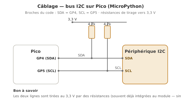
I2C needs pull-up resistors to VCC on SDA and SCL (≈ 4.7 kΩ, or 2.2 kΩ at 3.3 V). Most modules include them: nothing to add for a first try with a single module.
| Module | Pico |
|---|---|
| VCC | 3.3 V (or 5 V depending on the module) |
| GND | GND |
| SDA | GP4 |
| SCL | GP5 |
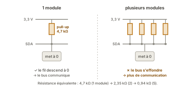
With several modules, their pull-ups end up in parallel: the equivalent resistance drops and the bus can no longer pull back up. You then keep a single active pair (see the “too many” pitfall).
3. Scan the addresses (built in)
Before any application code, i2c.scan() lists the addresses that answer — no need for a separate scanner sketch:
from machine import I2C, Pin
i2c = I2C(0, scl=Pin(5), sda=Pin(4))
print([hex(a) for a in i2c.scan()])     # e.g. ['0x76']
If the list is empty: check the wiring (SDA/SCL not swapped, pull-ups, supply). Typical addresses: SSD1306 OLED = 0x3C, BMP280 = 0x76/0x77, DS3231/MPU6050 = 0x68.
4. Read a device with its library
Once the address is confirmed, install the driver (see libraries), import it, read. At the lowest level the raw API is i2c.readfrom(addr, n) / i2c.writeto(addr, buf) / i2c.readfrom_mem(addr, reg, n), but a library wraps up those accesses almost every time.
Example — Reading a BMP280 (pressure and temperature)
Library: a MicroPython bmp280 driver (through Thonny’s package manager or mip, see libraries).
from machine import I2C, Pin
from bmp280 import BMP280       # name depends on the driver installed
from time import sleep

i2c = I2C(0, scl=Pin(5), sda=Pin(4))
print("Addresses:", [hex(a) for a in i2c.scan()])

capteur = BMP280(i2c)           # default address 0x76

while True:
    print("T =", capteur.temperature, "°C   P =", capteur.pressure, "Pa")
    sleep(1)
Breathe on the module: the temperature rises. (The exact API depends on the driver you choose. The scan() stays the common diagnostic step.)
Pitfalls
Wrong address. A driver set to 0x77 while the module is at 0x76: the device cannot be found. Always start with scan().
Pull-ups missing or too many. With no pull-up the bus floats. Too many pull-up modules in parallel → the equivalent resistance gets too low and the bus no longer holds. Disable the pull-ups on every module but one.
Incompatible VCC level. A 3.3 V module powered at 5 V → destruction. For mixed buses, a two-way level shifter (a PCA9306, or a BSS138 circuit).
Address clash. Two identical sensors at the same address (0x68) → the bus is corrupted. Move an address strap, or use an I2C multiplexer (TCA9548A).
SDA/SCL swapped. scan() finds nothing. Check the pin assignment.
Cables too long. I2C tolerates ~1-2 m in standard mode with correctly sized pull-ups. Beyond that, corrupted frames. Shorten, screen, or move to a differential bus.
Special case — Several buses, or the same address
The Pico has two controllers (I2C0 and I2C1 on separate pins): you spread the load, or isolate two devices sharing an address. An alternative for several identical devices on a single bus: a TCA9548A multiplexer (8 channels).
Where it fits in the project
- Step 2 of the proof of concept phase — every I2C sensor or display is validated in two moves:
scan()for the address, a library example for the reading. - Step 4 of the concept phase — I2C imposes itself from 2 or more devices, or when GPIO pins are scarce.
i2c.scan() is the bus’s universal diagnostic tool: in a few seconds it separates a hardware problem (nothing answers) from a software one (the device answers but the reading fails).
See also
- MicroPython — the module hub
- Communication buses — I2C among the buses
- SPI · UART — the alternatives
- OLED display — a typical use of I2C
- Using a library — for I2C sensors
- I2C — the cross-cutting concept page
- Logic levels — for mixed 3.3 / 5 V buses
- I2C on Arduino — the C++ equivalent (
Wire.h)