SPI (Serial Peripheral Interface) is a synchronous serial bus on 4 wires — SCK (clock), MOSI (Master Out Slave In), MISO (Master In Slave Out) and CS (Chip Select). It offers far higher rates than I2C (several MHz), at the cost of more pins. In MicroPython you reach it through the SPI class of the [[micropython-modules-en|machine]] module, CS being a plain Pin handled by hand. It is the bus of SD cards, of TFT displays, of radio modules (NRF24L01, LoRa). The Pico’s advantage: it runs at 3.3 V, like SD cards — often no level shifter needed (unlike a 5 V Uno).
What is it for?
Three uses: storing data on an SD card (datalogger, logs); driving a graphical display (TFT, e-paper); communicating by radio (NRF24L01, LoRa). Where I2C addresses several devices on 2 wires, SPI selects one at a time through its CS pin. Each extra device costs a GPIO.
Step by step
Four steps: create the SPI object, wire it with a dedicated CS, install the library, write the code.
1. Create the SPI object
The Pico has two controllers (SPI0, SPI1). SCK/MOSI/MISO sit on compatible pins. CS is a free GPIO, handled by the code:
from machine import SPI, Pin
spi = SPI(0, baudrate=1_000_000, sck=Pin(2), mosi=Pin(3), miso=Pin(4))
cs = Pin(5, Pin.OUT)
cs.value(1)        # device deselected at rest (CS is active low)
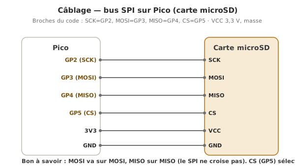
2. Wire it with a dedicated CS
| SD module | Pico |
|---|---|
| VCC | 3.3 V |
| GND | GND |
| MISO | GP4 |
| MOSI | GP3 |
| SCK | GP2 |
| CS | GP5 (any GPIO) |
Several SPI devices share SCK/MOSI/MISO, but each has its own CS on a separate GPIO.
3. Install the library
For the SD card: the sdcard driver (Thonny’s package manager or mip, see libraries). For a display: st7789, ili9341… depending on the model.
4. Write the code (SD card)
You mount the card into the file system (os.mount), then read and write like any other file:
from machine import SPI, Pin
import sdcard, os

spi = SPI(0, baudrate=1_000_000, sck=Pin(2), mosi=Pin(3), miso=Pin(4))
cs = Pin(5, Pin.OUT)

sd = sdcard.SDCard(spi, cs)
os.mount(sd, "/sd")             # the card becomes the /sd folder

with open("/sd/test.txt", "w") as f:
    f.write("Hello SD card\n")

with open("/sd/test.txt") as f:
    print(f.read())

os.umount("/sd")
How to read this code
os.mount(sd, "/sd")grafts the SD card into the Pico’s file system: from there,/sd/...is handled exactly like a local file. Thewith open(...) as f:block opens the file and closes it on its own at the end of the block. The write is then really recorded, with noclose()by hand as in Arduino.os.umount("/sd")detaches the card cleanly before you pull it out.
Insert a microSD formatted in FAT32, run it, watch the REPL. Read the card back on a PC to check test.txt.
Example — Datalogger on an SD card
Read an ADC measurement and write it, timestamped, every 5 s.
from machine import SPI, Pin, ADC
from time import ticks_ms, ticks_diff
import sdcard, os

spi = SPI(0, baudrate=1_000_000, sck=Pin(2), mosi=Pin(3), miso=Pin(4))
sd = sdcard.SDCard(spi, Pin(5, Pin.OUT))
os.mount(sd, "/sd")

capteur = ADC(Pin(26))
dernier = ticks_ms()
INTERVALLE = 5000

while True:
    if ticks_diff(ticks_ms(), dernier) >= INTERVALLE:
        dernier = ticks_ms()
        val = capteur.read_u16()
        with open("/sd/data.csv", "a") as f:      # "a" = append at the end
            f.write("{},{}\n".format(ticks_ms(), val))
        print("Logged:", val)
Let it run, pull the card out, open data.csv in a spreadsheet. Note the "a" mode (append), so as not to overwrite at every write.
Pitfalls
CS left unhandled. With several devices, leaving one CS active (low) all the time: several devices answer on MISO, corrupted reads. Initialise every CS to 1 (inactive) and only activate at the moment of access.
SD card not detected. Causes: wrong formatting (try FAT32), unreliable connections, a baudrate too high for breadboard wiring (start low, ~1 MHz). Check the MISO/MOSI/SCK wiring.
Forgetting os.mount. With no mount, /sd/... does not exist: os.mount(sd, "/sd") after creating the SDCard object, and umount before pulling the card.
Overwriting instead of appending. Opening in "w" on every pass rewrites the file. For a log, use "a" (append).
Cables too long for fast SPI. At several MHz, long Dupont wires introduce reflections and crosstalk. Keep under 10 cm on breadboard, lower the baudrate if it is unstable.
SPI mode set wrong. SPI has 4 modes (clock polarity and phase). The drivers handle them, but for raw access, check polarity/phase in the device’s datasheet.
Special case — Software SPI
SoftSPI (from the machine module) emulates SPI on arbitrary GPIO, at a lower rate: useful for isolating a troublesome device on its own lines, or when the hardware pins are taken.
Where it fits in the project
- Step 2 of the proof of concept phase — an SD datalogger built early captures field trials away from a screen.
- Step 3 of the integration and testing phase — an on-board datalogger that records every variable is the best weapon against the intermittent bugs that only show up during a demo.
SPI becomes unavoidable as soon as you want to write files (SD), display graphics (TFT) or do fast wireless. Choosing your CS pins well from the start avoids the clashes.
See also
- MicroPython — the module hub
- Communication buses — SPI among the buses
- I2C · UART — the alternatives
- Using a library —
sdcard, display drivers - SPI — the cross-cutting concept page
- SPI on Arduino — the C++ equivalent (
SPI.h,SD.h)