A display lets a project show its readings, its state or its menu without a PC. Two families coexist: graphical OLEDs (128×64 pixels on an SSD1306, modern) and character LCDs (16×2). Both are covered here through their most teachable version: I2C, which takes only two pins. In MicroPython the SSD1306 OLED is driven by the ssd1306 driver, which draws into a buffer pushed to the screen by show().
What is it for?
A display matters as soon as a project leaves the PC bench and becomes standalone: demonstration (live readings on the enclosure), interface (menu, mode), status indicator (time, battery, error).
| Type | Graphics | Current draw |
|---|---|---|
| 0.96″ OLED SSD1306 (128×64) I2C | ✅ | ~20 mA |
| 16×2 LCD I2C (through a PCF8574) | none | ~20–50 mA (backlight) |
For a first project: the SSD1306 OLED — small, readable, simple graphics.
Step by step
Four steps: wire the I2C bus, install the driver, draw into the buffer, push it to the screen.
1. Wire the I2C bus
4 wires: VCC → 3.3 V (consumer SSD1306 boards accept 3.3/5 V); GND → GND; SDA → GP4; SCL → GP5. Confirm the address with i2c.scan() (usually 0x3C).
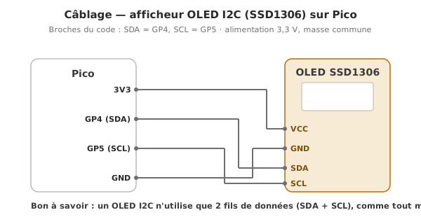
2. Install the driver
The ssd1306 driver is installed through the Thonny package manager or with mip (see Using a library).
3. Draw into the buffer
from machine import I2C, Pin
from ssd1306 import SSD1306_I2C

i2c = I2C(0, scl=Pin(5), sda=Pin(4))
oled = SSD1306_I2C(128, 64, i2c)        # 0x3C by default

oled.fill(0)                            # clears the buffer (0 = black)
oled.text("Hello", 0, 0)                # text (x, y in pixels)
oled.text("Line 2", 0, 12)
oled.show()                             # pushes the buffer to the screen
SSD1306_I2C derives from framebuf, so pixel(), line(), rect(), hline() and fill_rect() are available too.
4. Refresh in a loop
from time import ticks_ms, sleep_ms

while True:
    oled.fill(0)
    oled.text("Time: {} s".format(ticks_ms() // 1000), 0, 0)
    oled.show()
    sleep_ms(500)
How to read this code
oled.show()is mandatory: the library draws into a buffer (in RAM) and only that call sends it to the screen.fillandtexttouch the buffer alone. Untilshow()is called, the screen stays frozen. Forgettingshow()means a black screen while the code “runs”.
Example — OLED thermometer (two I2C devices on one bus)
Read the temperature from a BMP280 (see I2C) and show it on the OLED. The bus carries both devices, at different addresses: BMP280 0x76, OLED 0x3C.
from machine import I2C, Pin
from ssd1306 import SSD1306_I2C
from bmp280 import BMP280
from time import sleep_ms

i2c = I2C(0, scl=Pin(5), sda=Pin(4))
oled = SSD1306_I2C(128, 64, i2c)
capteur = BMP280(i2c)

while True:
    t = capteur.temperature
    oled.fill(0)
    oled.text("Temperature", 0, 0)
    oled.text("{:.1f} C".format(t), 20, 28)     # 8 px text (framebuf, no scaling)
    oled.show()
    sleep_ms(500)
Breathe on the BMP280: the displayed temperature rises. A simple demo combining two I2C devices on a single bus.
Pitfalls
Wrong I2C address. The SSD1306 sits at 0x3C almost always, sometimes at 0x3D. Run i2c.scan() before hard-coding the address.
Forgetting show(). The driver draws into a buffer. Only show() sends it to the hardware. Forget it and the screen stays black despite correct code.
Wrong driver (SSD1306 vs SH1106). Some “OLED” boards use an SH1106 controller, which the SSD1306 driver offsets by a few pixels. If the image is shifted or clipped, switch to the sh1106 driver.
No accented characters. The ssd1306 font is ASCII: é, è and à do not render. Write without accents, or use an extended driver and font.
Text off screen. At 128×64 the base font is 8 px tall: about 8 lines of about 16 characters each. Beyond that the text runs off. Size it accordingly.
Several I2C pull-ups. An OLED alongside other boards carrying pull-ups drops the equivalent resistance too low and destabilises the bus. Disable the pull-ups on all but one.
An LCD that does not clear. An I2C LCD writes character by character without erasing the rest: overwrite with spaces, or call clear(). (MicroPython drivers such as i2c_lcd have to be installed.)
Special case — SPI and e-paper screens
For colour TFT screens (ST7789, ILI9341) or e-paper, the bus is usually SPI, with a dedicated driver (st7789 and others). More pins, more bandwidth, colour images, or the very low power draw of e-paper.
Where it fits in the project
- Step 3 of the proof of concept phase — the first embedded display, to watch readings without a PC.
- Step 3 of the integration and testing phase — the built-in display acts as the HMI for the tests (current mode, real values).
A display, however simple, moves a project from “watching the REPL” to “seeing the state directly”. A qualitative leap in demonstration, for two pins and a driver.
See also
- MicroPython — the module hub
- I2C in MicroPython — prerequisite (bus wiring)
- Using a library — installing
ssd1306 - SPI in MicroPython — for TFT and e-paper screens
- OLED display (Arduino) — the C++ equivalent