A module is a small prefabricated PCB carrying one main component (a sensor, a driver, a converter) surrounded by its minimal application circuit: power, pull-ups, decoupling, connector. Modules save you all the low-level wiring from the datasheet. What is left is plugging in four Dupont wires and calling the library. This page covers the generic wiring of a module, and the pitfalls that make a freshly received module refuse to start. The logic is the same whatever the board. Only the pin numbers and the Pico’s 3.3 V constraint change.
What is it for?
A school project carries 5 to 15 modules: a sensor (DHT11, HC-SR04, BMP280, MPU6050), a driver (L298N, DRV8833), a display (I2C OLED), communication, power, a utility board (DS3231 RTC, MicroSD). They all follow the same wiring logic, and getting it right once saves hours of fumbling.
Step by step
Four steps: identify the pins, check the supply voltage, wire signals and ground, check the pull-ups.
1. Identify the module’s pins
Four recurring families: power (VCC/VIN/+ and GND/−); logic signals (SCL/SDA for I2C, SCK/MOSI/MISO/CS for SPI, TX/RX for UART, or plain GPIO); configuration (jumpers for address, voltage, pull-up); power terminal block (driver modules). When the pinout is not obvious, look for the module’s own page or search “module XXX pinout”.
2. Check the supply voltage it accepts
Since the Pico runs at 3.3 V, this is the number one trap:
- 3.3–5 V module (most modern modules, regulated I2C boards) — tolerant, read the silkscreen;
- 5 V only module — power it from 5 V (VBUS), but its output signals will be at 5 V: shift them before they reach a Pico pin (logic levels);
- 3.3 V only module — power it from 3.3 V, never from 5 V.
On the signal side, a module that drives 5 V into a Pico input calls for a voltage divider or a level shifter. A 3.3 V module driven from the Pico (3.3 V) connects directly.
3. Wire signals and ground
The rule that never bends: the module’s ground (GND) must be tied to the Pico’s ground, even when the supplies are separate. Without a shared GND, the signals have no reference, and the module does not answer. A useful discipline: red for VCC, black for GND, short Dupont wires (under 20 cm) for I2C/SPI, connectors pushed fully home.
4. Check the pull-ups and the configuration
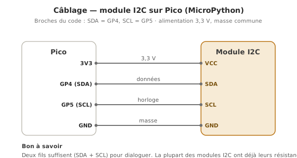
Many I2C modules carry their own pull-ups on SDA/SCL (around 4.7 kΩ). Handy for a first attempt, but stacking I2C modules puts all those pull-ups in parallel: the equivalent resistance gets too low and the bus stops working. Symptom: one module works alone, two together do not, so remove the pull-up jumpers on all but one. Other frequent jumpers: I2C address selection, voltage selection, opto enable on a relay module.
Example — Wiring a DHT11 module (temperature and humidity)
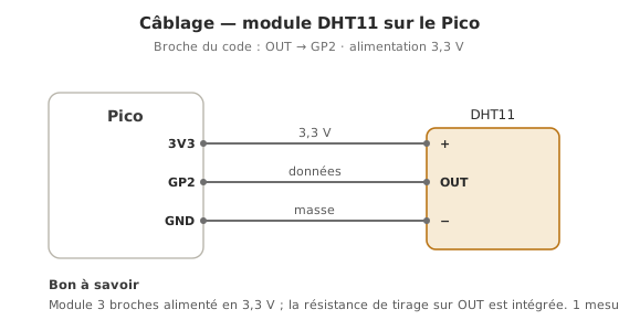
DHT11 module: 3 pins (+ 3.3–5 V, OUT 1-wire signal, − GND), with a 10 kΩ pull-up built onto OUT.
Wiring: + → 3.3 V; − → GND; OUT → GP2.
Library: the dht module is built into the firmware (see libraries).
from machine import Pin
import dht
from time import sleep

capteur = dht.DHT11(Pin(2))     # DHT11 sensor on GP2

while True:
    sleep(2)                 # 1 reading/s max on a DHT11; 2 s leaves some margin
    capteur.measure()        # triggers a reading (1-wire protocol, wrapped)
    print("T =", capteur.temperature(), "°C   H =", capteur.humidity(), "%")
Watch it in the REPL. Breathing on the sensor pushes the humidity up.
Pitfalls
Mixing up VCC and signal. Wiring OUT to 3.3 V (instead of GP2) does not release any smoke, but the module does not answer. Check the wiring before every attempt.
Missing GND. Module powered but GND not connected: the module looks alive (its LED is on) but no signal gets through. Always connect GND as soon as you connect VCC.
Powering a hungry module from a pin. A Wi-Fi or GSM module draws peaks of several hundred mA: the Pico’s 3.3 V output (which is limited) cannot hold, and the board reboots. A stable external supply for hungry modules.
Incompatible logic levels. A module that drives 5 V (HC-SR04) into a Pico input damages it. Check the tolerance — logic levels.
Several I2C pull-ups in parallel. 2 modules at 4.7 kΩ give 2.35 kΩ; at 5 modules, around 940 Ω, which is often too low. Disable the pull-ups on all but one.
A counterfeit module. On the most widespread part numbers, counterfeits pass the first tests and then drift. For serious work, use a known source.
Special case — A module with no datasheet
Generic modules (HW-XXX, KY-XXX) with no supplier behind them. Leads: look up the part number of the main soldered component (its datasheet does exist), search part-number pinout in images, or identify the pins with a multimeter. See reading a datasheet.
Where it fits in the project
- Step 2 of the proof of concept phase — every module gets validated on its own (power, GND, signals, first example) before integration.
- Step 2 of the integration and testing phase — requalification inside the integrated system (multiple pull-ups, shared supply, bus conflicts).
A module wired properly at the start of the PoC is a subsystem you never revisit, and validating it on its own keeps hardware problems from muddying the software work.
See also
- MicroPython — the module hub
- Using a shield or expansion board — the stacked alternative
- Using a library — to drive the module
- I2C · SPI · UART — depending on the module’s bus
- Logic levels — 3.3 and 5 V compatibility
- Reading a datasheet — check voltage, current, signals
- Wiring a module (Arduino) — the C++ equivalent