UART (Universal Asynchronous Receiver-Transmitter) is a point-to-point serial bus on two wires: TX (transmit) and RX (receive), crossed over between two devices. In MicroPython you reach it through the UART class of the [[micropython-modules-en|machine]] module. You use it to make the Pico talk to another microcontroller or an external module (a NEO-6M GPS, an HC-05 Bluetooth module, an RFID reader). Unlike the Arduino Uno, the Pico’s REPL console goes over USB (USB-CDC) rather than over a hardware UART: the Pico’s two UARTs therefore stay free for modules — no need for SoftwareSerial.
What is it for?
UART is the simplest bus: 2 wires, no shared clock, minimal setup (baud rate plus format). Typical cases: talking between 2 microcontrollers, reading a GPS module (NMEA frames at 9600 baud), dialoguing with a Bluetooth or Wi-Fi module in AT mode, driving a serial display. The limit: UART is point-to-point (1 ↔ 1). For several devices, use a second UART, or move to I2C/SPI.
Step by step
Four steps: identify the UARTs, wire them crossing TX/RX, set the baud rate, write the code.
1. Identify the Pico’s UARTs
The Pico exposes two hardware UARTs, UART0 and UART1, assignable to several pins depending on the pinout:
| UART | TX (default) | RX (default) |
|---|---|---|
UART0 | GP0 | GP1 |
UART1 | GP4 | GP5 |
The REPL console is on USB, independent: you keep print() going to Thonny while using UART0 for a module. That is simpler than on a Uno, where the single UART is shared with USB.
2. Wire it crossing TX/RX
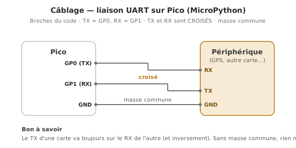
An inviolable rule: TX on one side → RX on the other. A common GND is compulsory.
| Pico | External device |
|---|---|
| TX (GP0) | → RX |
| RX (GP1) | ← TX |
| GND | — GND |
3. Set the baud rate
The baud rate must be identical at both ends (9600, 115200…). The module documents its default rate (HC-05: 9600, NEO-6M GPS: 9600). Frame format: 8N1 by default (8 bits, no parity, 1 stop bit).
4. Write the code
from machine import UART, Pin
from time import sleep

uart = UART(0, baudrate=9600, tx=Pin(0), rx=Pin(1))

while True:
    if uart.any():                 # any bytes available?
        data = uart.read()         # read everything waiting (bytes)
        print("Received:", data)
    uart.write(b"ping\n")          # transmit (bytes, not str)
    sleep(1)
uart.any() gives the number of bytes received. uart.read() / uart.readline() read. uart.write() transmits. You handle bytes (b"..."), not str — convert as needed (texte.encode() / data.decode()).
Example — Communication between two Picos
A Pico A sends a counter. A Pico B receives it, decodes it, displays it.
Wiring: A GP0 (TX) → B GP1 (RX), A GP1 (RX) ← B GP0 (TX), common GND.
Pico A (transmitter):
from machine import UART, Pin
from time import sleep

uart = UART(0, baudrate=9600, tx=Pin(0), rx=Pin(1))
compteur = 0

while True:
    uart.write("{}\n".format(compteur).encode())   # frame terminated by \n
    print("Sent:", compteur)
    compteur += 1
    sleep(1)
Pico B (receiver):
from machine import UART, Pin

uart = UART(0, baudrate=9600, tx=Pin(0), rx=Pin(1))

while True:
    if uart.any():
        ligne = uart.readline()        # read up to the \n (bytes)
        if ligne:
            valeur = int(ligne.decode().strip())   # bytes → text → integer
            print("Received:", valeur)
readline() reads up to the \n marker: that is how the receiver knows where a value ends.
Pitfalls
TX/RX not crossed over. Mistake number one: TX→TX, RX→RX. Nothing gets through. TX on one side → RX on the other.
Baud rate mismatched. The same baud at both ends, otherwise the symbols make no sense.
No common GND. With no shared ground there is no reference: the link does not work, even with two supplies.
Confusing bytes and str. uart.write("texte") fails: it wants bytes (.encode()), and uart.read() returns bytes (.decode() for text).
Incompatible logic levels. A module putting out 5 V on the Pico’s RX (3.3 V) damages it: a voltage divider or a level shifter (logic levels).
Frame poorly delimited. With no end marker (\n), the receiver does not know where a value ends. Use readline() or a structured protocol.
Reading without checking any(). uart.read() with no data returns None. Testing uart.any() (or handling None) avoids an error.
Special case — A USB-to-serial adapter for debugging
A USB-to-serial adapter (CH340, CP2102) links the PC to a UART without going through the Pico: intercepting a bus, testing a Bluetooth or Wi-Fi module in AT mode directly, programming a chip that has no USB. A bench tool well worth having for debugging.
Where it fits in the project
- Step 2 of the proof of concept phase — isolated validation of a UART module (GPS, Bluetooth) before integration.
- Step 3 of the proof of concept phase — a command bus between subsystems when the architecture splits perception and command across several MCUs.
- Step 2 of the integration and testing phase — check that the buses hold at full load (throughput, reliability, interference).
UART is the bus to learn first: 2 wires, and the gateway to a host of modules. On the Pico, the advantage is that its 2 hardware UARTs are free, the console being on USB.
See also
- MicroPython — the module hub
- The REPL — the console (on USB), distinct from the hardware UARTs
- Communication buses — UART among the buses
- I2C · SPI — for several devices
- UART — the cross-cutting concept page
- UART on Arduino — the C++ equivalent (and
SoftwareSerial)