UART (Universal Asynchronous Receiver-Transmitter) is a point-to-point serial bus on two wires: TX (transmit) and RX (receive), crossed over between two devices. It is the bus underneath the IDE’s serial monitor (between the Arduino and the computer, through the USB chip) and also the one used to make two Arduino boards talk to each other, or an Arduino talk to an external module (a NEO-6M GPS, an HC-05 Bluetooth module, a PN532 RFID reader). This page concentrates on the UART link to an external module, as opposed to the link back to the computer, already covered in serial monitor.
What is it for?
UART is the simplest bus to put to work: 2 wires, no shared clock, minimal setup (baud rate plus frame format). Use cases on a school project:
- Getting 2 Arduino boards to talk on the same robot (one for sensing, one for control, say).
- Reading a GPS module (NEO-6M, NEO-8M) — NMEA text frames out at 9600 baud.
- Talking to a Bluetooth or Wi-Fi module (HC-05, HC-06, ESP-01 in AT mode).
- Driving a serial display (a 16×2 LCD with a serial module, some OLED displays).
A structural limit: UART is point-to-point (1 transmitter ↔ 1 receiver). To connect several devices you need either several UARTs (the Mega has 4 hardware UARTs), or a switch to I2C or SPI, which support several devices.
Step by step
Four steps: find the UARTs available, wire it with TX/RX crossed over, set the baud rate, write the code.
1. Find the UARTs available
| Board | Hardware UARTs | Pins |
|---|---|---|
| Uno R3, Nano | 1 (UART0, shared with USB) | D0 (RX), D1 (TX) |
| Uno R4 | 1 hardware plus 1 separate USB | D0/D1 (hardware), USB independent |
| Mega 2560 | 4 (UART0, UART1, UART2, UART3) | D0/D1, D19/D18, D17/D16, D15/D14 |
| ESP32 | 3 | configurable |
Classic mistake: UART/USB clash on the Uno R3
On the Uno R3, the one hardware UART is shared with USB. Using
Serialto talk to an external module takes over pins D0/D1, the same ones as the USB cable. A very common result on student projects: the upload fails for as long as the module stays wired to D0/D1 (avrdude: stk500_recv(), port not responding…), and the error message never points at the real cause. You lose time looking at the code or at the port. Two reflexes: unplug the module from D0/D1 before every upload, or (much better) useSoftwareSerial, a library that emulates a UART on any pair of GPIO pins and leavesSerial/USB free.
On the Uno R4 the problem goes away: Serial (USB) and Serial1 (pins D0/D1) are two independent hardware UARTs. An external module plugs into D0/D1 and is driven with Serial1, while the USB serial monitor stays live: SoftwareSerial is no longer needed for a single module.
2. Wire it with TX/RX crossed over
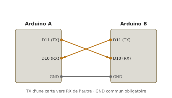
The inviolable rule of UART: TX on one side → RX on the other. The Arduino’s TX transmits, so it goes to the RX of the device that receives. Symmetrically, the Arduino’s RX receives whatever the device sends on its TX.
| Arduino | External device |
|---|---|
| TX | → RX |
| RX | ← TX |
| GND | — GND |
A common GND is compulsory. The device’s VCC is independent (a separate supply is often recommended for hungry modules such as the HC-05).
3. Set the baud rate
The baud rate (bits per second) must be the same at both ends. Common values: 9600, 19200, 38400, 57600, 115200 baud. The external module has a documented default baud rate (HC-05: 9600; NEO-6M GPS: 9600; ESP-01 in AT mode: 115200 historically, 9600 on some versions).
Frame format: 8N1 (8 data bits, no parity, 1 stop bit) is the near-universal convention. No need to state it on Arduino, it is the default.
4. Write the code
Case a — hardware UART on the Mega (uses Serial1, Serial2…):
void setup() {
  Serial.begin(115200);   // for the computer
  Serial1.begin(9600);    // for the external module on D19/D18
}

void loop() {
  // Read what the module sends, post it back to the computer
  if (Serial1.available()) {
    char c = Serial1.read();
    Serial.print(c);
  }
  // Read what the computer sends, pass it on to the module
  if (Serial.available()) {
    char c = Serial.read();
    Serial1.print(c);
  }
}
How to read this code
The
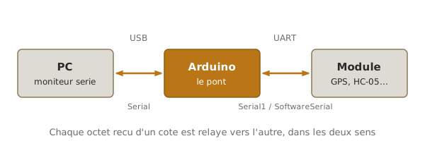
loop()is a two-way bridge. The firstifasksSerial1: “have you received a byte from the module?” (available()returns the number of bytes waiting). If it has, you read it (read()) and copy it over to the computer (Serial.print). The secondifdoes the opposite, from the computer to the module. Nothing blocks: on every pass ofloop(), at most one character moves in each direction.
Case b — SoftwareSerial on the Uno:
#include <SoftwareSerial.h>

const int RX_BROCHE = 10;  // virtual RX
const int TX_BROCHE = 11;  // virtual TX
SoftwareSerial monSerie(RX_BROCHE, TX_BROCHE);

void setup() {
  Serial.begin(115200);   // for the computer
  monSerie.begin(9600);   // for the external module on D10/D11
}

void loop() {
  if (monSerie.available()) {
    char c = monSerie.read();
    Serial.print(c);
  }
  if (Serial.available()) {
    char c = Serial.read();
    monSerie.print(c);
  }
}
The loop() is the same as in case a: only the communication object changes (monSerie instead of Serial1). This “serial bridge” pattern is there to watch what a module says on the monitor, and to send it commands from the monitor.
Example — Communication between two Arduino boards
The full case: Arduino A sends a counter. Arduino B receives it, decodes it and prints it on the serial monitor.
Wiring (the same TX↔RX crossover as in the diagram of step 2):
- Arduino A D11 (SoftwareSerial TX) → Arduino B D10 (SoftwareSerial RX)
- Arduino A D10 (RX) ← Arduino B D11 (TX)
- GND A — GND B (compulsory)
Arduino A code (transmitter):
#include <SoftwareSerial.h>
SoftwareSerial lien(10, 11);  // RX, TX

int compteur = 0;

void setup() {
  Serial.begin(115200);
  lien.begin(9600);
}

void loop() {
  lien.print(compteur);
  lien.print('\n');  // end-of-frame marker
  Serial.print("Sent: "); Serial.println(compteur);
  compteur++;
  delay(1000);
}
Arduino B code (receiver):
#include <SoftwareSerial.h>
SoftwareSerial lien(10, 11);  // RX, TX

void setup() {
  Serial.begin(115200);
  lien.begin(9600);
}

void loop() {
  if (lien.available()) {                        // at least one byte has arrived
    String trame = lien.readStringUntil('\n');   // gather up to the end-of-frame marker '\n'
    int valeur = trame.toInt();                  // turn the text received back into an integer
    Serial.print("Received: ");
    Serial.println(valeur);
  }
}
Upload to each Arduino, then open a serial monitor for each board: two IDE windows on two different COM ports are enough, each Arduino showing up on its own port. You see the counter sent on one side and received on the other.
Pitfalls
TX/RX not crossed over. The number one beginner’s mistake: wiring TX→TX and RX→RX. The system looks powered but no communication gets through. TX on one side → RX on the other, always.
Mismatched baud rate. Both ends must have the same .begin(N). Otherwise unreadable symbols come out, just as with a badly set serial monitor.
No common GND. A UART link with no shared GND does not work: the logic levels have no common reference. Always tie GND, even if each board has its own supply.
SoftwareSerial unstable at high rates. The library emulates a UART by bit-banging and reaches its limits beyond 38400 baud. For higher rates, prefer a hardware UART (the Mega) or a Wi-Fi/Bluetooth module that negotiates its own rate internally.
Clash with USB on the Uno R3. Using Serial (UART0) to talk to an external module on D0/D1 takes over the same pins as USB: the upload fails until you unplug the module. On the Uno, prefer SoftwareSerial for external modules.
Incompatible logic levels. Wiring the TX of a 3.3 V module (an ESP-01) to the RX of a Uno R3 (5 V) generally works in that direction (the Uno reads 3.3 V as HIGH). The other way round (Uno TX at 5 V onto ESP-01 RX at 3.3 V) can damage the ESP. A voltage divider or a level shifter is compulsory. See logic levels.
Badly delimited frame. Sending Serial.print(123) on side A and reading Serial.read() on side B gives '1', '2', '3' separately. With no end-of-frame marker (a newline '\n', or a specific character), the receiver has no idea where a value ends. Use readStringUntil('\n') or a structured protocol.
UART buffer overflow. The receive buffer is 64 bytes by default on the Uno. If you transmit faster than the receiver reads, the extra bytes are lost silently. Watch the rate, or impose a software flow control (an acknowledgement after every frame).
Special case — USB-to-serial adapter for debugging
A USB-to-serial adapter (FTDI FT232, CH340, CP2102) connects the computer to a UART without going through an Arduino. Handy for:
- Watching what passes between the Arduino and an external module, by tapping the bus (with a Y).
- Programming a board with no built-in USB (a bare ATmega328, an ESP-01).
- Testing a Bluetooth or Wi-Fi module in AT mode straight from the computer, before integrating it with the Arduino.
A very useful tool for embedded debugging: it lets you watch or drive a UART from the computer without tying up an Arduino board.
Where it fits in the project
- Step 2 of the proof of concept phase — validating a UART module (GPS, Bluetooth) on its own before integrating it into the system.
- Step 3 of the proof of concept phase — the command bus between subsystems when the architecture splits sensing and control across several MCUs.
- Step 2 of the integration and testing phase — checking that the buses hold up at full load (rate, reliability, interference).
UART is the bus to learn first, for two reasons: it serves the computer-side debugging, and it is the gateway to a great many common modules. Mastering the “serial bridge” pattern (routing the computer to a module in two lines) saves an enormous amount of time in commissioning.
See also
- Arduino — hub of the Arduino tutorials
- Serial monitor — UART to the computer, the prerequisite
- Communication buses — UART among the buses available
- I2C on Arduino · SPI on Arduino — for several devices
- Logic levels — 3.3 V against 5 V on TX/RX
- UART — the cross-cutting concept page