SPI (Serial Peripheral Interface) is a synchronous serial bus on 4 wires — SCK (clock), MOSI (Master Out Slave In), MISO (Master In Slave Out) and SS (Slave Select, also written CS). It offers markedly higher rates than I2C (several MHz in practice) at the price of more pins. It is the bus of choice for SD cards, TFT displays, wireless modules (NRF24L01, LoRa SX1276) and some fast sensors (high-frequency accelerometers).
What is it for?
Three emblematic uses on a school project:
- Storing data on an SD card — a datalogger of sensor readings, an archive of GPS frames, debugging logs.
- Driving a graphic display — a 2.4″ ILI9341 TFT, a Waveshare e-paper display.
- Talking over radio — NRF24L01 modules (2.4 GHz) for short-range remote control, LoRa for long range.
Where I2C networks several devices on 2 wires through addressing, SPI explicitly selects one device at a time with its SS pin: every additional device costs one more GPIO pin.
Step by step
Four steps: find the SPI pins, wire it with a dedicated SS, install the library, write the code.
1. Find the board’s SPI pins
| Board | SCK | MOSI | MISO | SS (default) |
|---|---|---|---|---|
| Uno R3, Nano | D13 | D11 | D12 | D10 |
| Mega 2560 | D52 | D51 | D50 | D53 |
| Uno R4 | D13 | D11 | D12 | D10 |
| ESP32 (VSPI) | D18 | D23 | D19 | D5 |
SCK, MOSI and MISO are fixed (hard-wired to the SPI controller), SS sits on D10 by convention but can be any GPIO pin: it is the application code that chooses which pin to pull LOW to address a device.
2. Wire it with a dedicated SS
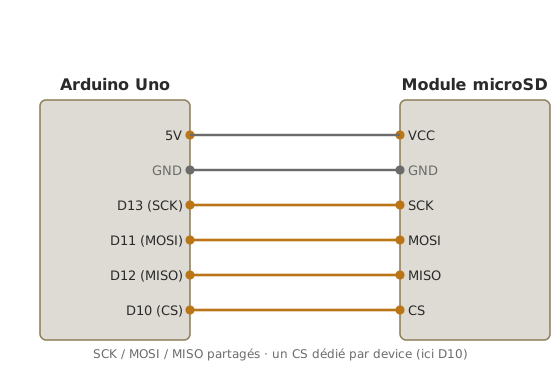
Generic wiring for an SD card module:
| SD module | Arduino Uno |
|---|---|
| VCC | 5 V (or 3.3 V depending on the module — check) |
| GND | GND |
| MISO | D12 |
| MOSI | D11 |
| SCK | D13 |
| CS | D10 (or any other GPIO pin) |
With several SPI devices on the same bus (SD plus a TFT display, say), SCK/MOSI/MISO are shared, but each device has its own CS pin on a separate GPIO.
3. Install the library
For the SD card: SD.h ships with the IDE. Nothing to install. For other devices: Adafruit_GFX plus Adafruit_ILI9341 for TFT displays, RF24 for the NRF24L01, and so on. See using a library.
4. Write the code (SD card)
#include <SPI.h>
#include <SD.h>

const int CS_SD = 10;   // Chip Select pin of the SD card

void setup() {
  Serial.begin(115200);
  delay(2000);

  if (!SD.begin(CS_SD)) {   // start the card on the SPI bus
    Serial.println("Echec initialisation SD");
    while (1);              // no card: no point going on
  }
  Serial.println("SD OK");

  // Open (or create) a file for writing, then close it
  File f = SD.open("test.txt", FILE_WRITE);
  if (f) {                 // f is invalid if the open fails: always test it
    f.println("Hello SD card !");
    f.println(millis());
    f.close();             // close() forces the actual write to the card
    Serial.println("Ecrit");
  } else {
    Serial.println("Echec ouverture fichier en ecriture");
  }

  // Read the file back, character by character
  f = SD.open("test.txt");
  if (f) {
    while (f.available()) Serial.write(f.read());  // while bytes remain, print them
    f.close();
  }
}

void loop() {}
How to read this code
Writing to an SD card always follows the same cycle:
SD.open(nom, FILE_WRITE)opens (or creates) a file and returns aFileobject. You write to it withprintlnjust as on the serial monitor.close()is compulsory: it is what forces the actual write to the card (withoutclose(), the file can stay empty). Reading back reopens the file and walks through it withwhile (f.available()): while bytes remain, you read them one at a time. Theif (f)test after every open is essential: an invalidFileraises no error, it fails silently.
Insert a microSD card formatted as FAT16 or FAT32 (32 GB or less for FAT32), upload, watch the serial monitor. Take the card out and read it on a computer to check the test.txt file.
Example — Temperature datalogger on an SD card
The full case: read a sensor (a potentiometer as a stand-in for temperature) and write the timestamped reading to the SD card every 5 seconds.
Wiring: SD module on SPI (D10-D13, as in the diagram of step 2), potentiometer on A0 (wired as a divider: see reading an analog sensor).
#include <SPI.h>
#include <SD.h>

const int CS_SD  = 10;                       // Chip Select of the SD card
const int CAPTEUR = A0;                      // sensor (a potentiometer here) on A0
const unsigned long INTERVALLE = 5000;       // logging period: 5 s
unsigned long dernierEnreg = 0;              // time of the last log entry

void setup() {
  Serial.begin(115200);
  if (!SD.begin(CS_SD)) {
    Serial.println("SD KO");
    while (1);                                 // no card: block here
  }
}

void loop() {
  // non-blocking rate: act only once 5 s have elapsed (see arduino-temporisation)
  if (millis() - dernierEnreg >= INTERVALLE) {
    dernierEnreg = millis();
    int val = analogRead(CAPTEUR);             // read the sensor (0-1023)

    File f = SD.open("data.csv", FILE_WRITE);  // open in append mode
    if (f) {
      f.print(millis()); f.print(","); f.println(val);  // one CSV line: timestamp,value
      f.close();
      Serial.print("Loggue : t="); Serial.print(millis()); Serial.print(" val="); Serial.println(val);
    }
  }
}
Let it run for a few minutes, take the card out, open data.csv in a spreadsheet — a timestamp column in milliseconds, a value column. Plot the curve to check the stability.
Pitfalls
CS not handled in parallel. With several SPI devices, forgetting to deselect the unused CS lines (leaving them HIGH) means several devices drive MISO at once and the readings are corrupted. At start-up: pinMode(CS_X, OUTPUT); digitalWrite(CS_X, HIGH); for every device.
SD module not detected. The usual causes: card badly formatted (try FAT32), card too big (over 32 GB: move to exFAT, which needs an advanced SD library such as SdFat), dubious connections, supply level (some SD modules want 3.3 V).
5 V logic levels on a 3.3 V SD module. Many SD modules include their own 3.3 V regulator and a level shifter on the SPI pins — MISO, MOSI, SCK, CS. Others do not, and putting 5 V onto the SPI pins kills the card. Check the module’s documentation.
SPI mode or bit order badly set. SPI has 4 modes (0 to 3) depending on the polarity and phase of the clock. The official libraries handle it. For direct code through SPI.beginTransaction(), read the device’s datasheet. The SD card uses mode 0.
Bus shared with an ethernet shield or a Wi-Fi module. A CS clash, or libraries that do not release the bus cleanly. Symptom: sometimes the SD works, sometimes the ethernet does. Fix: bracket every SPI access with SPI.beginTransaction() and SPI.endTransaction() (most modern libraries do it automatically).
Cables too long, or breadboard, for SD. SPI at 4 MHz or more is sensitive to the length of jumper leads (reflections, crosstalk). For a serious project, shorten the path by soldering or use a proto shield. On the test bench, keep the leads under 10 cm.
Open for writing that fails silently. SD.open(..., FILE_WRITE) returns an invalid File object if the open fails. Always test if (f) before writing.
Special case — Software SPI against hardware SPI
Every SPI pin can be emulated in software (bit-banging) on ordinary GPIO pins, at the price of a markedly lower rate. Library: a software SPI library (SoftSPI, for instance) or code written by hand. Handy for boards with few hardware pins, or when you want to isolate a troublesome device entirely on its own lines.
Where it fits in the project
- Step 2 of the proof of concept phase — an SD datalogger as early as possible, to capture field trials away from a screen (vibration measurements, dry-run self-tests).
- Step 3 of the integration and testing phase — an on-board datalogger (SD) capturing every variable of the system is the best weapon against the intermittent bugs that only show up in a demonstration.
SPI is less universal than I2C on a beginner’s project, but it becomes unavoidable as soon as you want to write files (SD), show graphics (TFT) or talk fast over the air. Choosing your CS pins carefully from the start saves future clashes.
See also
- Arduino — hub of the Arduino tutorials
- Communication buses — SPI among the buses
- I2C on Arduino · UART on Arduino — the alternatives
- Using a shield — a great many SD and ethernet shields are SPI
- Using a library —
SD.h,Adafruit_GFX,RF24 - SPI — the cross-cutting concept page