A digital sensor delivers information encoded as a binary signal, as opposed to an analog sensor putting out a continuous voltage. The encoding varies: a simple logic level (present / absent), a pulse whose width encodes the measurement (an ultrasonic sensor), a proprietary 1-wire protocol (DHT11), or an I2C / SPI frame (BMP280, MPU6050). This page covers the first two cases: the I2C and SPI buses have tutorials of their own.
What is it for?
Digital sensors are the most widely used measuring bricks on a school project: detecting a presence (PIR), measuring a distance (HC-SR04 ultrasonic), spotting something going past (an infrared sensor). Measuring a rotational speed (an encoder) is a neighbouring but distinct case: that is pulse counting, handled by interrupts or timers, not by digitalRead() or pulseIn(). What they gain over analog sensors: immunity to cable noise, a value already conditioned, a direct reading with no electrical calibration. What they cost: you depend on the sensor’s documentation (protocol, timing, library).
Step by step
First identify the type of signal, then put the method to work on two proximity sensors: an IR threshold sensor read with a plain digitalRead (the minimal case), then the HC-SR04 ultrasonic sensor, which measures the distance through a pulse (wiring, datasheet, code).
1. Identify the type of signal
Three common families:
- Logic level — the sensor puts out
HIGHorLOWdepending on an event (presence or absence detected). Examples: PIR sensor (movement), inductive presence sensor, magnetic limit switch. Read with a plaindigitalRead(). - Timed pulse — the sensor emits a pulse whose width encodes the measurement. Example: the HC-SR04 ultrasonic sensor (width = the round trip of the wave, hence the distance). Read with
pulseIn(). - Proprietary protocol — a structured binary sequence that only a dedicated library knows how to decode. Examples: DHT11 (1-wire), DS18B20 (1-wire Dallas). Read through a library (see using a library).
The sensor’s datasheet or product page always says which of the three families it belongs to.
2. The simplest case — an IR threshold sensor
Before the ultrasonic sensor, the minimal case: a sensor that puts out HIGH or LOW directly, read with a digitalRead(). On the distance theme, the common example is the IR obstacle detection module (the FC-51 kind): it sends out an infrared beam and flips its output when an obstacle reflects that beam from closer than a threshold set by an on-board potentiometer. Three wires, no timing at all.
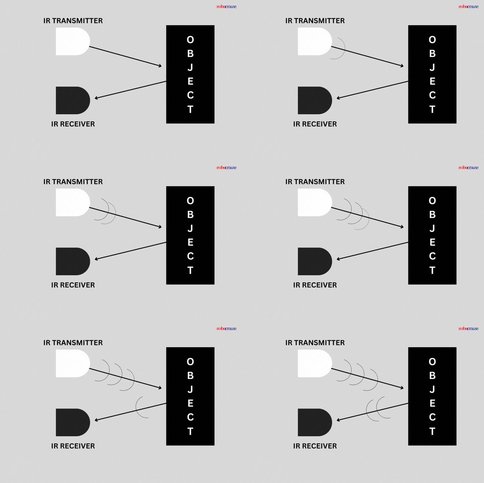
VCC→+5 V,GND→GND,OUT→ pin D2 (input)
const int IR  = 2;
const int LED = 13;

void setup() {
  pinMode(IR, INPUT);                       // output already conditioned by the module
  pinMode(LED, OUTPUT);
  Serial.begin(115200);
}

void loop() {
  bool obstacle = (digitalRead(IR) == LOW); // this module: LOW = obstacle detected
  digitalWrite(LED, obstacle);              // LED lit if an obstacle is close
  Serial.println(obstacle ? "Obstacle" : "Clear");
  delay(200);
}
The only subtlety is the active level: most of these modules are active low (OUT falls to LOW when an obstacle is detected), hence the == LOW test, to be checked on the product page. No debouncing: unlike a button (a mechanical contact, see off input), the output is electronic and already clean. This sensor only signals a threshold crossed. To measure the actual distance, see the next case.
3. Wire the HC-SR04
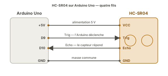
A richer case: the HC-SR04 (ultrasonic) measures the distance instead of signalling a threshold (an emblematic school-project sensor, present in every kit):
- sensor
VCC→ Arduino+5 V - sensor
GND→ ArduinoGND - sensor
Trig→ pin D9 (output: the trigger pulse) - sensor
Echo→ pin D10 (input: the return pulse)
4. Read the HC-SR04 datasheet
The HC-SR04 works on time of flight: the transmitter sends out a burst of ultrasound, the wave travels, bounces off the object, then comes back to the receiver. By measuring the round-trip time and knowing the speed of sound, you get the distance. That time is exactly what the Echo pin gives back, and what the code will read at the next step.
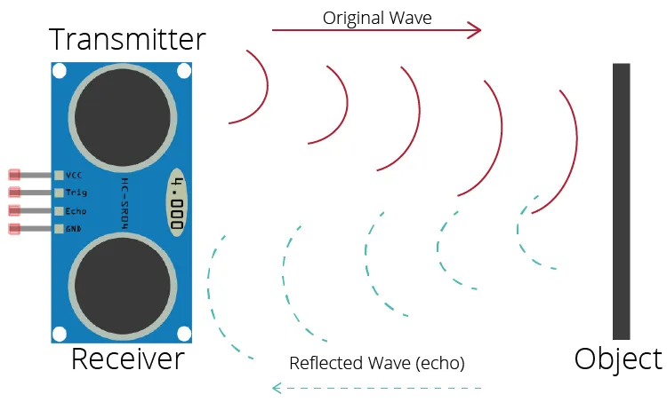
The datasheet gives the parameters this principle relies on:
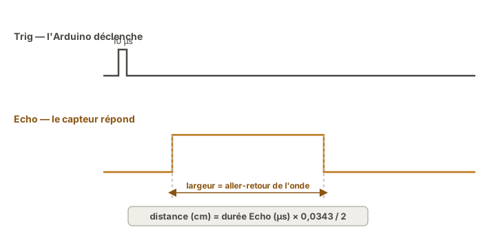
- The sensor waits for a 10 µs pulse on
Trigto start a measurement. - It then generates a pulse on
Echowhose duration is proportional to the round-trip time of the sound wave. - Speed of sound ≈ 343 m/s at 20 °C. Distance = duration × 343 / 2 (round trip).
- Useful range: 2 cm to 4 m.
Echovoltage: 5 V, compatible with the Uno R3, to be adapted on the ESP32 (see logic levels).
5. Write the code
const int TRIG = 9;                 // trigger pin (output)
const int ECHO = 10;                // return echo pin (input)

void setup() {
  pinMode(TRIG, OUTPUT);            // TRIG: the Arduino writes to it
  pinMode(ECHO, INPUT);             // ECHO: the Arduino reads from it
  Serial.begin(115200);            // serial link, to print the distance
}

void loop() {
  // Trigger: one CLEAN 10 µs pulse on TRIG
  digitalWrite(TRIG, LOW);          // start from a clean low state...
  delayMicroseconds(2);             // ...settled for 2 µs
  digitalWrite(TRIG, HIGH);         // rising edge: the pulse begins
  delayMicroseconds(10);            // held for 10 µs (the duration the sensor requires)
  digitalWrite(TRIG, LOW);          // back to rest: the pulse has been sent

  // Measure: pulseIn() waits for the ECHO pulse and returns its duration (µs)
  unsigned long duree_us = pulseIn(ECHO, HIGH, 30000UL);  // 30000 = 30 ms timeout

  if (duree_us == 0) {              // 0 = no echo before the timeout (out of range)
    Serial.println("Out of range");
  } else {
    float distance_cm = duree_us * 0.0343 / 2;  // duration -> distance (see the note)
    Serial.print(distance_cm);
    Serial.println(" cm");
  }

  delay(100);                       // one measurement every 100 ms (~10 Hz)
}
How to read this code. Two moves only. Trigger: you impose a clean 10 µs pulse on TRIG. The initial LOW (2 µs) guarantees a clean rising edge, and it is that 10 µs duration the sensor waits for before firing a burst of ultrasound. Measure: pulseIn(ECHO, HIGH, 30000UL) puts the program on hold for the pulse on ECHO and returns its duration in microseconds, the round-trip time of the wave. A 0 means no echo came back before the deadline (30 ms), so the target is out of range. The conversion × 0.0343 / 2 turns that duration into a distance: 0.0343 cm/µs is the speed of sound, and you divide by two because the wave makes the outward trip and the return.
Move your hand towards the sensor and away from it. The distance appears on the serial monitor:
23.45 cm
18.22 cm
12.07 cm
7.65 cm
Out of range
8.90 cm
Two decimal places, because Serial.print() prints two by default on a float (an accuracy the sensor does not have). And Out of range shows up as soon as your hand leaves the measuring cone: that is the 0 returned by pulseIn() at the end of the 30 ms.
Example — Threshold detector with a warning LED
The full case: if an object enters a close zone (< 20 cm), light a warning LED.
const int TRIG  = 9;
const int ECHO  = 10;
const int LED   = 13;
const float SEUIL_CM = 20.0;        // warning distance in cm

void setup() {
  pinMode(TRIG, OUTPUT);
  pinMode(ECHO, INPUT);
  pinMode(LED,  OUTPUT);
  Serial.begin(115200);
}

// Returns the distance in cm, or -1 if there is no echo (see the note in step 5)
float mesurerDistance() {
  // Trigger and measure block, identical to step 5
  digitalWrite(TRIG, LOW);  delayMicroseconds(2);
  digitalWrite(TRIG, HIGH); delayMicroseconds(10);
  digitalWrite(TRIG, LOW);
  unsigned long d = pulseIn(ECHO, HIGH, 30000UL);
  return (d == 0) ? -1.0 : d * 0.0343 / 2;   // -1 = out of range, otherwise the distance
}

void loop() {
  float d = mesurerDistance();               // one measurement
  if (d > 0 && d < SEUIL_CM) {               // valid object AND inside the close zone
    digitalWrite(LED, HIGH);                 // warning: LED lit
    Serial.print("ALERT: "); Serial.print(d); Serial.println(" cm");
  } else {
    digitalWrite(LED, LOW);                  // nothing in the zone: LED out
  }
  delay(100);
}
Factoring the work into a mesurerDistance() function points towards the practice of organising embedded code (see firmware and debugging a program).
Pitfalls
Confusing digital with analog. A logic-level presence sensor is read with digitalRead(), not with analogRead(). The other way round, an LM35 temperature sensor is analog despite its techy name: it puts out a continuous voltage, to be read with analogRead() (see reading an analog sensor).
pulseIn() timeout badly set. With no explicit timeout, pulseIn() blocks for up to 1 s (its default) if no echo comes back (target too far, absorbent surface). Always pass a third argument (in microseconds). For the HC-SR04 at 4 m: ~23 ms round trip, so a 30 ms timeout.
Ignoring outliers. The HC-SR04 sometimes returns nonsense readings (interference, a poor reflection). Filter them (a median over 3-5 readings, or a threshold on the variation between consecutive readings) before driving an actuator from the output (see filtering measurements).
5 V level on an ESP32 input. The HC-SR04 puts Echo out at 5 V. On an ESP32 (a 3.3 V tolerant input), wiring it straight damages the pin. A voltage divider or a level shifter (see logic levels).
Broken or outdated library for the DHT11/22. These sensors have strict timing and several competing libraries. Check that the library you use is maintained (recent commits) and compatible with the target board: R3, R4 and ESP32 are not the same thing.
Measuring too often. The HC-SR04 has a measurement cycle of about 60 ms (the time it takes for the echo to die away). Measuring faster (every 10 ms) gives inconsistent results. 10 Hz (every 100 ms) is a good rhythm.
PIR sensor not settled. A PIR needs 30 to 60 seconds of thermal settling after power-up. Reading its output during that time gives noise. Plan a delay(30000) in setup(), or an indicator showing the settling state.
Special case — Sensors on the I2C or SPI bus
A great many modern sensors (BMP280, MPU6050, MAX30102, VL53L0X) talk over a bus: they are digital, but in a category of their own. See I2C on Arduino and SPI on Arduino. The wiring and the code differ radically from a pulse or logic-level reading.
Where it fits in the project
- Step 2 of the proof of concept phase — every sensor in the project is validated on its own before integration: wiring, raw reading, measuring range observed.
- Step 1 of the integration and testing phase — every sensor is requalified on its own before the integration tests.
Wiring a sensor, reading its documentation, getting a credible measurement out of it over a few minutes: that is the loop that makes the PoC. Doing it quickly and properly on a standalone sensor, in the right order, is the move to make automatic for every sensor in the project.
See also
- Arduino — hub of the Arduino tutorials
- Reading an analog sensor — the continuous alternative (potentiometer, LM35, LDR)
- I2C on Arduino — the bus for more advanced digital sensors (BMP280, MPU6050)
- Using a library — for the DHT11, DS18B20 and so on
- Reading a datasheet — to identify the exact nature of the signal
- Filtering measurements — to smooth sensor noise