An analog sensor puts out a continuous voltage proportional to the quantity being measured. On Arduino, you read that voltage through the built-in analog-to-digital converter (ADC), with the analogRead() function. Typical sensors: potentiometer (rotation), LDR (light level), LM35 / TMP36 (temperature), FSR force sensor, MQ-x gas sensor. This page covers the ADC reading, the calibration and the pitfalls specific to analog signals.
What is it for?
A great many physical phenomena are naturally measured as a voltage: light intensity, temperature, the position of a slider, an applied force. The sensor turns the phenomenon into a 0-5 V (or 0-3.3 V) voltage, the Arduino turns that into an integer you can compute with. The move to master is less the reading itself (one line of code) than the correct conversion between the raw integer and the physical quantity.
Step by step
Four steps: know your ADC, wire it, read it, convert it.
1. Know your ADC
| Board | Resolution | Integer range | Full-scale voltage | Reference |
|---|---|---|---|---|
| Uno R3 (ATmega328P) | 10 bits | 0 - 1023 | 5 V | AREF or internal 1.1 V |
| Mega 2560 | 10 bits | 0 - 1023 | 5 V | AREF or internal 1.1 / 2.56 V |
| Uno R4 (Renesas RA4M1) | 10 bits by default, 12/14 bits possible | 0 - 1023 (up to 16383) | 5 V | AREF or internal |
| Nano (ATmega328P) | 10 bits | 0 - 1023 | 5 V | AREF or internal 1.1 V |
| ESP32 | 12 bits | 0 - 4095 | 3.3 V | internal |
On the Uno R3: one analogRead() returns an integer between 0 (pin at GND) and 1023 (pin at 5 V). The resolution is therefore 5 V / 1024 ≈ 4.88 mV per step.
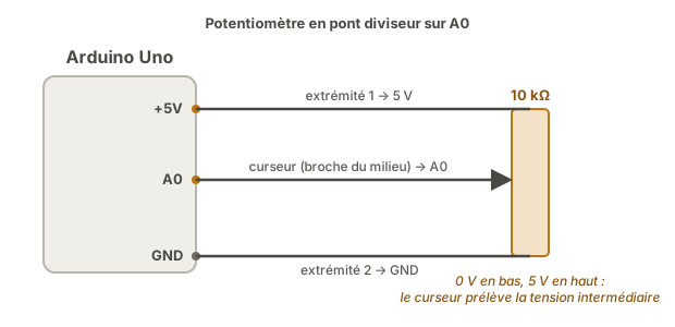
2. Wire a potentiometer
For this first example: a 10 kΩ potentiometer, three pins (the concept page covers how it works).
- End pin 1 → Arduino
+5 V - End pin 2 → Arduino
GND - Wiper (middle pin) → Arduino
A0
The potentiometer forms a voltage divider whose output varies linearly from 0 V (wiper hard over on the GND side) to 5 V (wiper hard over on the 5 V side).
3. Raw reading
const int CAPTEUR = A0;

void setup() {
  Serial.begin(115200);
}

void loop() {
  int valeur = analogRead(CAPTEUR);   // reads the voltage on A0 → 0 to 1023
  Serial.println(valeur);             // prints the raw value
  delay(100);                         // ~10 readings per second
}
Turn the potentiometer and watch the values on the serial monitor: 0 to 1023 (on the Uno R3). At mid-travel, around 512.
4. Convert into a physical quantity
The conversion depends on the sensor. Three examples:
Potentiometer as a 0-100% setpoint:
int valeur = analogRead(A0);                 // 0 to 1023 (10-bit full scale)
float pourcentage = valeur * 100.0 / 1023.0; // rule of three: 1023 → 100%
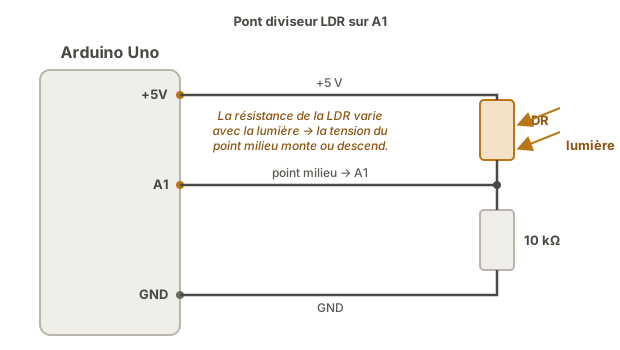
LDR as a light level: an LDR plus a fixed resistor in a voltage divider gives a voltage that depends on the light. No direct physical unit: you often keep the raw value, or calibrate by thresholds (< 200 = dark, > 800 = bright).
LM35 as a temperature sensor: the LM35 puts out 10 mV per °C. At a 5 V full scale:
int valeur = analogRead(A0);             // 0 to 1023
float tension_V = valeur * 5.0 / 1023.0; // raw integer → voltage (5 V full scale)
float temperature_C = tension_V * 100.0; // the LM35 law: 10 mV/°C → ×100
Serial.print(temperature_C);
Serial.println(" °C");
How to read this code. The conversion happens in two steps: the raw integer first becomes a voltage (valeur × 5 / 1023, where 5 V is the ADC’s full scale), then that voltage becomes a physical quantity according to the sensor’s law (here 10 mV per °C, hence × 100). The whole art is dividing by the right full scale and applying the right law: that is the move to repeat for every sensor.
The TMP36, often mentioned alongside the LM35, does not follow the same law: it adds an offset of 0.5 V, so temperature_C = (tension_V - 0.5) * 100.
Example — Potentiometer as an adjustable threshold
A full case combining an analog reading with a binary output: a potentiometer sets a threshold above which an LED lights, according to another analog input (an LDR, for instance).
Wiring: potentiometer on A0, LDR plus a 10 kΩ resistor as a voltage divider on A1, LED plus 220 Ω on D13.
const int POT      = A0;
const int LUMIERE  = A1;
const int LED      = 13;

void setup() {
  pinMode(LED, OUTPUT);
  Serial.begin(115200);
}

void loop() {
  int seuil    = analogRead(POT);      // 0-1023
  int lumiere  = analogRead(LUMIERE);  // 0-1023

  digitalWrite(LED, lumiere < seuil ? HIGH : LOW);

  Serial.print("Threshold: "); Serial.print(seuil);
  Serial.print("\tLight: "); Serial.println(lumiere);
  delay(50);
}
The output on the serial monitor (and on the serial plotter) lets you watch threshold and measurement at once, useful for setting the threshold by eye and then freezing it as a constant.

Pitfalls
Confusing analogRead() with digitalRead(). analogRead(A0) returns an integer 0-1023, digitalRead(A0) returns HIGH/LOW according to the logic threshold. An analog sensor read with digitalRead() gives 0 or 1 depending on whether the voltage passes ~2.5 V, a massive loss of information.
Analog pin that does not exist. On the Uno, A0-A5 are analog. On the Nano, A0-A7, but A6 and A7 only work as analog inputs (not as digital GPIO). On the ESP32, ADC1 and ADC2 pins: ADC2 is unavailable while Wi-Fi is active (a classic trap).
ADC range depending on the resolution. By default the Uno R4 returns 0-1023 (10 bits) like the Uno R3: an R3 sketch runs as it stands. But switch to high resolution with analogReadResolution(12) or (14) and analogRead() returns 0-4095 or 0-16383: any code that divides by a hard-coded 1023 becomes wrong. The fix: convert by dividing by the real full scale, never by a frozen constant.
Voltage reference left unspecified. By default the ADC compares against the board’s supply voltage. If the Arduino is powered over USB from a computer putting out 4.8 V instead of 5 V, the full scale is 4.8 V: every measurement is 4% off. For accurate measurements, use analogReference(INTERNAL) (a stable internal 1.1 V) or an external reference on AREF.
Noise on the measurements. A raw analog reading typically carries ±1 to ±3 LSB of noise (~5-15 mV). On an accurate sensor (an LM35 at 0.01 V/°C → 1 LSB = 0.5 °C), that counts. Filter it: average over 10-20 readings (oversampling), or a hardware RC low-pass filter (see filtering measurements).
Input voltage out of range. Wiring a voltage above 5 V to an analog pin on the Uno R3 damages the ADC. Check the sensor’s output range in its datasheet (see reading a datasheet).
Cables too long with no ground. A sensor cable over 30-50 cm with GND poorly referenced makes a perfect 50 Hz aerial. Symptom: the reading swings by ±20 LSB with nothing happening. Bring GND back, shorten it, or screen it.
Special case — Sensors on 3.3 V against 5 V
A great many modern sensors (Adafruit sensors, Grove modules) put out 0-3.3 V instead of 0-5 V. Wired to a Uno R3 (whose ADC is referenced to 5 V), the sensor’s full scale only reaches analogRead() ≈ 675 (3.3 / 5 × 10²³), not 1023. Three answers:
- Live with it — convert
valeur × 3.3 / 1023instead of× 5 / 1023. You lose about a third of the resolution. - Use
AREF— wireAREFto 3.3 V, declareanalogReference(EXTERNAL), get the full resolution back. CallanalogReference(EXTERNAL)before the firstanalogRead(): otherwise the internal reference ends up shorted onto the voltage onAREF, which can damage the ADC. - Use a natively 3.3 V board — ESP32, Uno R4 Minima as an option, STM32. See logic levels.
Where it fits in the project
- Step 2 of the proof of concept phase — every analog sensor is validated on a raw reading plus a conversion into a physical quantity, ideally compared against a reference (a shop thermometer for the LM35, a light meter for the LDR, a multimeter for the potentiometer).
- Step 1 of the integration and testing phase — every sensor is requalified before the integration tests: useful range, effective resolution, residual noise.
Working through the calibration is the step that turns a sensor “wired up and spitting out a number” into an instrument, without which everything downstream is calibrated on sand.
See also
- Arduino — hub of the Arduino tutorials
- Reading a digital sensor — the on/off or pulse alternative
- Serial monitor — watching the raw readings and calibrating
- Filtering measurements — smoothing ADC noise
- Accuracy, trueness, precision — resolution is not accuracy, systematic error against noise, calibration
- Logic levels — 3.3 V against 5 V on sensors and boards
- Reading a datasheet — to find the sensor’s voltage range