An analog sensor delivers a continuous voltage proportional to the quantity being measured. On the Pico you read that voltage through the built-in analog-to-digital converter (ADC), by way of the ADC class of the [[micropython-modules-en|machine]] module. Typical sensors: potentiometer (rotation), LDR (light level), LM35 / TMP36 (temperature), FSR force sensor. This page covers the ADC reading, the conversion and the pitfalls of analog signals.
What is it for?
A great many phenomena are measured as a voltage: light level, temperature, the position of a slider, force. The sensor turns the phenomenon into a 0-3.3 V voltage, the Pico turns that into an integer you can compute with. The move to master is less the reading itself (one line) than the correct conversion between the raw integer and the physical quantity.
Step by step
Four steps: know your ADC, wire it, read it, convert it.
1. Know the Pico’s ADC
The Pico has a 12-bit ADC, but MicroPython exposes read_u16(), which scales the reading onto 16 bits (0-65535) for consistency across boards. The reference is fixed at 3.3 V (no adjustable reference as on Arduino).
| Board | Real resolution | read_u16() | Full scale |
|---|---|---|---|
| Pico / Pico 2 | 12 bits | 0 – 65535 (scaled) | 3.3 V |
| ESP32 | 12 bits | 0 – 65535 | 3.3 V (adjustable attenuation) |
The analog inputs are GP26, GP27, GP28. An internal channel (ADC(4)) measures the chip’s temperature.
2. Wire a potentiometer
A 10 kΩ potentiometer: one end → 3.3 V, the other → GND, wiper (middle) → GP26. The potentiometer forms a voltage divider varying from 0 V to 3.3 V.
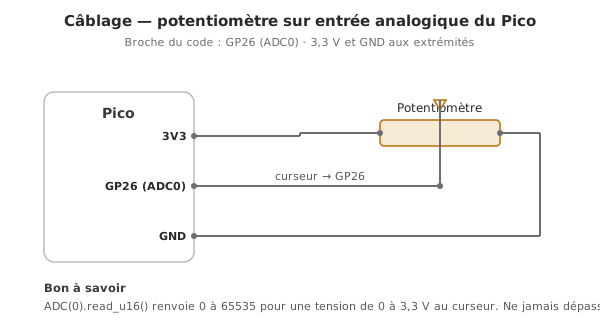
3. Raw reading
from machine import ADC, Pin
from time import sleep

pot = ADC(Pin(26))      # or ADC(26); analog input on GP26

while True:
    print(pot.read_u16())   # 0 to 65535 (12 bits scaled onto 16)
    sleep(0.1)              # ~10 readings per second
Turn the potentiometer: 0 to 65535, around 32768 at mid-travel.
4. Convert into a physical quantity
Potentiometer as a 0-100% setpoint:
pourcentage = pot.read_u16() * 100 / 65535 # rule of three: 65535 → 100%Voltage:
tension = pot.read_u16() * 3.3 / 65535 # raw -> volts (3.3 V reference, 65535 full scale)Chip temperature (internal channel, formula from the RP2040 datasheet):
from machine import ADC
capteur = ADC(4)                                 # internal channel (CORE_TEMP)
def temperature_c():
    v = capteur.read_u16() * 3.3 / 65535         # voltage of the internal sensor
    return 27 - (v - 0.706) / 0.001721           # RP2040 law: 0.706 V at 27 °C, -1.721 mV/°C
How to read this code. The conversion happens in two steps: the raw value (read_u16(), 0-65535) first becomes a voltage (you divide by the 65535 full scale and multiply by the 3.3 V reference), then that voltage becomes a physical quantity according to the sensor’s law (here the formula of the internal sensor). The whole art is dividing by the right full scale (65535, not 4095, read_u16() already scaling the 12-bit reading) and applying the right law: that is the move to repeat for every sensor.
Example — Potentiometer as an adjustable threshold
Read a potentiometer (GP26) as a threshold, an LDR (GP27) as the measurement, light an LED when the light falls below the threshold.
from machine import ADC, Pin
from time import sleep

pot     = ADC(Pin(26))           # potentiometer = adjustable threshold
lumiere = ADC(Pin(27))           # LDR = light measurement
led     = Pin(15, Pin.OUT)

while True:
    seuil = pot.read_u16()                       # 0 to 65535
    mesure = lumiere.read_u16()
    led.value(1 if mesure < seuil else 0)        # LED on if the light falls below the threshold
    print("Threshold:", seuil, " Light:", mesure)
    sleep(0.05)
The output at the REPL (and Thonny’s plotter) lets you watch threshold and measurement at once to calibrate, then freeze the threshold as a constant.
Pitfalls
Confusing the ADC with Pin.value(). pot.read_u16() returns 0-65535. Reading the same pin as a digital input would give 0 or 1 — a massive loss of information.
Non-ADC pin. Only GP26 / GP27 / GP28 are analog inputs on the Pico. (On the ESP32, ADC2 is unavailable while Wi-Fi is running — a classic trap.)
Believing in an adjustable reference. On the Pico the reference is fixed (3.3 V). You always convert against 3.3 V. A noisy 3.3 V supply biases every measurement — decouple it properly.
Noise on the measurements. A raw reading carries a few LSB of noise. On an accurate sensor that counts: average over 10-20 readings (oversampling), or a hardware RC filter (see filtering measurements).
Input voltage out of range. Applying more than 3.3 V to an ADC input damages the chip (the Pico is not 5 V tolerant). Check the sensor’s output range in its datasheet (reading a datasheet).
Cables too long with no ground. A cable over 30-50 cm poorly referenced becomes a 50 Hz aerial: the reading swings with nothing happening. Shorten it, bring GND back, or screen it.
Special case — 5 V sensors
A sensor putting out 0-5 V goes past the Pico’s range (3.3 V). Answers: a voltage divider on the sensor’s output (a loss of resolution), or a natively 3.3 V board or sensor. See logic levels.
Where it fits in the project
- Step 2 of the proof of concept phase — every analog sensor is validated on a raw reading plus a conversion, ideally compared against a reference (thermometer, light meter, multimeter).
- Step 1 of the integration and testing phase — requalification: useful range, effective resolution, residual noise.
Calibration turns a sensor “that spits out a number” into an instrument of measurement, without which everything downstream is calibrated on sand.
See also
- MicroPython — the module hub
- Reading a digital sensor — the on/off or pulse alternative
- The REPL — watching the readings and calibrating
- Filtering measurements — smoothing ADC noise
- Measurement accuracy — resolution is not accuracy, calibration
- Logic levels — 3.3 V against 5 V on sensors and boards
- Reading an analog sensor (Arduino) — the C++ equivalent