PWM (Pulse Width Modulation) puts out a fast square wave whose proportion of time spent high you can vary — the duty cycle. In MicroPython, the PWM class of the [[micropython-modules-en|machine]] module generates that signal. For a load that is slow compared with the frequency (LED, motor, heating element), the effect is equivalent to an average voltage adjustable from 0 to 3.3 V, without the pin ever producing any real intermediate voltage.
What is it for?
PWM varies the power delivered to a load without burning energy in a variable component. Three typical uses:
- Brightness of an LED — fading, animation, progressive indicator;
- Speed of a DC motor — paired with an H-bridge (see DC motor);
- Servo — the position is encoded by the width of a pulse (see servo).
It is also the basis of regulated heating and of the DC dimmer.
Step by step
Four steps: create the PWM object, set frequency and duty cycle, wire it, watch it.
1. Create a PWM object
On the Pico, every GPIO pin can generate PWM (no dedicated “~” pins as on Arduino):
from machine import Pin, PWM

led = PWM(Pin(15))
led.freq(1000)            # signal frequency, in Hz
led.duty_u16(32768)       # duty cycle on 16 bits: 32768 = 50%
Two settings: freq() (the frequency, freely chosen) and duty_u16() (the duty cycle, from 0 = 0% to 65535 = 100%, on 16 bits).
2. Wire a PWM LED
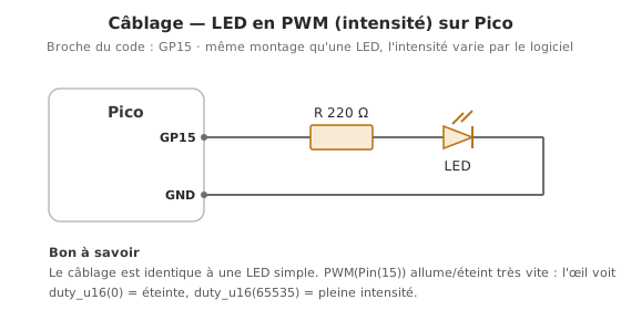
LED anode (+) → 220 Ω resistor → GP15, cathode (−) → GND. Same wiring as an on/off LED: it is the code that changes.
3. Write the code — progressive fade
from machine import Pin, PWM
from time import sleep_ms

led = PWM(Pin(15))
led.freq(1000)

while True:
    for d in range(0, 65536, 1024):     # fade up: 0 → 65535 in steps of 1024
        led.duty_u16(d)                 # applies the duty cycle
        sleep_ms(8)                     # 8 ms per step → a fade of about 0.5 s
    for d in range(65535, -1, -1024):   # fade down: 65535 → 0
        led.duty_u16(d)
        sleep_ms(8)
duty_u16(0) turns it off, duty_u16(65535) lights it fully. The LED lights up then dims progressively, over and over.
4. Watch it
To the naked eye, the LED varies in brightness (the effect of perceptual averaging). On an oscilloscope, you see its true nature: a 0-3.3 V square wave whose proportion of time high varies. To release the pin, led.deinit().
The exact look of that square wave on screen — period marked, duty cycle dimensioned — is detailed in oscilloscope.
Example — LED dimmer with a potentiometer
Read a potentiometer on GP26 and use it as the brightness setpoint. A MicroPython elegance: read_u16() (see reading an analog sensor) and duty_u16() are both on 16 bits, so you can wire one to the other with no scaling (unlike Arduino, where you have to divide 1023 → 255).
from machine import Pin, PWM, ADC
from time import sleep_ms

pot = ADC(Pin(26))
led = PWM(Pin(15))
led.freq(1000)

while True:
    led.duty_u16(pot.read_u16())   # 0..65535 -> 0..65535, directly
    sleep_ms(10)
Turn the potentiometer: the brightness follows.
Pitfalls
duty_u16() is on 16 bits, not 0-255. The duty cycle runs from 0 to 65535, not from 0 to 255 like Arduino’s analogWrite(). Passing 255 gives ~0.4% — almost off. (duty_u16() is the portable standard API of machine.PWM. Some ports also offer duty_ns() to set the pulse width in nanoseconds — available on the Pico —, while the older duty() 0-1023 survives on the ESP8266 and ESP32.)
Confusing PWM with a real analog output. PWM puts out a 0/3.3 V square wave with a variable duty cycle, not a voltage. The average is analog for a slow load. The instantaneous value stays binary. For a real voltage: an external DAC (an MCP4725 over I2C) or an RC filter.
Unsuitable frequency. A frequency too low makes an LED flicker, and a motor whine. Set freq() to suit the load (often 0.5-20 kHz). The Pico’s advantage: the frequency is free, unlike the ~490 Hz fixed by default on Arduino.
Inductive load with no flyback diode. A coil driven by PWM produces overvoltages at every switching: a 1N4007 diode reversed across it, otherwise the transistor dies.
PWM on a big load with no transistor. The duty cycle does not reduce the peak current: a 1 A motor draws 1 A during the high phases. The pin (~12 mA) cannot take it. Always a transistor (a MOSFET) or an H-bridge.
Forgetting deinit(). A pin left in PWM is no longer available as a plain GPIO. deinit() releases it.
Special case — Smoothing with an RC filter
To turn PWM into a real DC voltage (to drive the analog input of another instrument), an RC low-pass filter is enough (R = 10 kΩ, C = 1 µF → cut-off ~16 Hz, well below the PWM frequency). The trade-off: a response of a few tens of ms. For high precision, prefer a proper external DAC.
Where it fits in the project
- Step 2 of the proof of concept phase — every load with variable power (an LED with adjustable brightness, a fan, a DC motor) is first validated with PWM on an isolated bench.
- Step 3 of the proof of concept phase — the downstream command of a control loop often goes through PWM (see PID control).
- Step 3 of the integration and testing phase — driving the actuators integrated into the whole system.
PWM is the power-modulation tool par excellence — native on every pin of the Pico, well supported, enough for most of what you need in motor speed and brightness.
See also
- MicroPython — the module hub
- off output — prerequisite (switching transistors)
- Driving a DC motor — the flagship application, through an H-bridge
- Driving a servo — another kind of PWM
- PWM — the cross-cutting concept page
- Driving a PWM output (Arduino) — the C++ equivalent