A servo (short for servomotor) is a rotary actuator that moves to an angle setpoint carried by a pulse-width coded signal (0° to 180° on a standard servo). Unlike Arduino, which has the Servo.h library, MicroPython ships no servo class: you drive the servo straight from PWM, a 50 Hz signal whose pulse width you set (typically 0.5 to 2.5 ms). It is closer to the metal, and it shows exactly what a servo signal is.
What is it for?
The servo is the simplest actuator for controlled position movement: the steering of a robot (a steered wheel, a rudder, a movable sensor mount), sorting and switching, a gripper that opens and closes, aiming. Limit: a standard servo only covers about 180°. For continuous rotation, see continuous rotation servos (driven by speed) or the DC motor.
The servo signal
At 50 Hz (a 20 ms period), the position is coded by the width of the high pulse: ~0.5 ms = 0°, ~1.5 ms = 90° (mid-point), ~2.5 ms = 180° (the exact limits vary from one servo to the next, to be calibrated). In duty_u16 (0-65535 over 20 ms): 0.5 ms ≈ 1638, 1.5 ms ≈ 4915, 2.5 ms ≈ 8192.
Step by step
Four steps: choose the servo, wire it, write the angle-to-pulse conversion, drive it.
1. Choose the servo
| Reference | Voltage | Torque | Range | Use |
|---|---|---|---|---|
| SG90 (plastic gears) | 4.8-6 V | ~1.8 kg·cm | 0-180° | tests, light prototypes |
| MG90S (metal gears) | 4.8-6 V | ~2.2 kg·cm | 0-180° | grippers, repeated movement |
| MG996R | 4.8-7.2 V | 9-11 kg·cm | 0-180° | power actuators |
For a first test, the SG90 is the standard.
2. Wire it
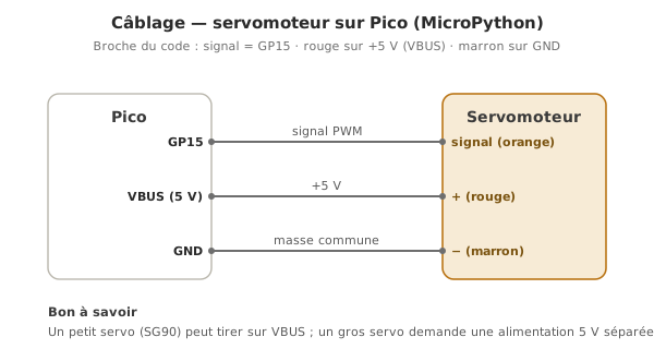
3 wires: red → +5 V (VBUS, or an external supply from two servos or one high-torque servo on); brown/black → GND; orange/yellow → the signal pin (say GP15). The Pico’s signal is 3.3 V, accepted by most servos. Shared GND if the supply is separate.
3. Convert an angle into a pulse
from machine import Pin, PWM

servo = PWM(Pin(15))
servo.freq(50)                 # 50 Hz = servo signal

MIN_DUTY = 1638                # ~0.5 ms (0°)   -- to calibrate
MAX_DUTY = 8192                # ~2.5 ms (180°) -- to calibrate

def angle(deg):
    deg = max(0, min(180, deg))           # clamp 0..180
    duty = int(MIN_DUTY + (deg / 180) * (MAX_DUTY - MIN_DUTY))
    servo.duty_u16(duty)
4. Drive it
from time import sleep

angle(90)      # mid-point
sleep(1)
while True:
    angle(0);   sleep(1)
    angle(90);  sleep(1)
    angle(180); sleep(1)
The servo goes to three positions. If it jitters without reaching the limits, adjust MIN_DUTY/MAX_DUTY (calibration, see Pitfalls).
Example — A sweep whose speed is set by a potentiometer
from machine import Pin, PWM, ADC
from time import sleep_ms

servo = PWM(Pin(15)); servo.freq(50)
pot = ADC(Pin(26))
MIN_DUTY, MAX_DUTY = 1638, 8192

def angle(deg):
    servo.duty_u16(int(MIN_DUTY + (max(0,min(180,deg))/180)*(MAX_DUTY-MIN_DUTY)))

a, sens = 0, 1
while True:
    pas = 1 + pot.read_u16() * 9 // 65535    # 1 to 10 degrees per step
    a += sens * pas
    if a >= 180: a, sens = 180, -1
    if a <= 0:   a, sens = 0, 1
    angle(a)
    sleep_ms(20)                              # ~50 Hz refresh
How to read this code
The back-and-forth rests on
sens, which is+1(climbing towards 180°) or-1(coming back down). On every pass,sens * pasis added. At the limit,sensis flipped and the servo sets off again. Thepasis taken from the potentiometer (read_u16()0-65535 → 1 to 10°): the larger the step, the faster the sweep.
Turning the potentiometer varies the sweep speed, handy for calibrating in a demo without reflashing.
Pitfalls
A frequency other than 50 Hz. Forgetting servo.freq(50), or leaving a high PWM frequency, means the servo does not understand the signal. 50 Hz, always.
Uncalibrated limits. Generic MIN_DUTY/MAX_DUTY values can drive the servo into its end stops: it strains, draws full current and heats up. Match the limits to the actual servo (tighten them if it hits a stop).
A Pico that reboots when the servo moves. The current peak of a servo (up to about 500 mA) pulls the voltage down: a separate supply for the servo, a shared GND.
No shared GND. A servo on its own battery with no ground tied back to the Pico: the signal has no reference, and the servo positions itself at random.
A servo that buzzes at rest. It is trying to reach a position that is mechanically blocked. servo.deinit() cuts the signal and leaves it passive.
Too many servos. Beyond two servos, an external supply is mandatory. For many servos, a dedicated I2C PWM driver (PCA9685, 16 channels) takes the load off the Pico.
Special case — Continuous rotation servos, and libraries
- A continuous rotation servo (FS90R and the like) turns at a speed proportional to the pulse: ~1.5 ms = stop, shorter or longer = one direction or the other. Useful for a small wheeled robot, in place of a DC motor plus an H-bridge. No position feedback.
- MicroPython servo libraries exist (installable through
mip, see libraries) and wrap the angle-to-pulse conversion. Driving the PWM directly, as above, remains the groundwork to understand.
Feedback servos
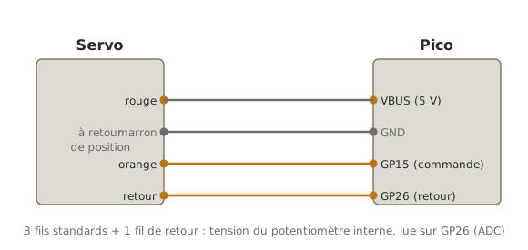
A standard servo commands a position but does not say whether it has actually reached it: angle(90) sends the setpoint, with no guarantee that the shaft really sits at 90° (a mechanical stop, an overload, an outside obstruction). A feedback servo answers that need by exposing a 4th wire that reports the measured angle, valuable on a 3-axis arm to know where the joints really are, not just where they were told to go.
A useful reminder: every analogue servo already positions itself in closed loop thanks to an internal potentiometer fixed to the shaft (that is what lets the servo “hold” its position). A feedback servo merely brings that signal out to a pin of the Pico.
Reading the position (analogue feedback)
The most common case is the analogue feedback servo (the Adafruit Analog Feedback Servo, for instance): the 4th wire gives the wiper voltage of the internal potentiometer straight out, an image of the angle. You read it on an ADC input (→ ADC).
from machine import Pin, PWM, ADC
from time import sleep_ms

servo = PWM(Pin(15)); servo.freq(50)
retour = ADC(Pin(26))            # 4th wire : internal potentiometer voltage
MIN_DUTY, MAX_DUTY = 1638, 8192

# ADC values read during calibration (to measure for EVERY servo)
ADC_0   = 7000                   # read_u16() with the servo at 0 deg
ADC_180 = 58000                  # read_u16() with the servo at 180 deg

def commande(deg):
    servo.duty_u16(int(MIN_DUTY + (deg/180)*(MAX_DUTY-MIN_DUTY)))

def angle_reel():
    brut = retour.read_u16()
    return (brut - ADC_0) * 180 // (ADC_180 - ADC_0)   # interpolation -> degrees

while True:
    commande(90)                 # setpoint : go to 90 deg
    sleep_ms(500)
    print("Setpoint 90 -> measured", angle_reel(), "deg")
    sleep_ms(500)
How to read this code
The setpoint (
commande) and the measurement (angle_reel) are two independent things: one tells the servo where to go, the other reads where it really is. TheADC_0andADC_180limits cannot be guessed, they are calibrated: you command the servo to 0° then to 180°, readread_u16()at each end, and the interpolation converts between the two. Every servo has its own limits (the potentiometer is never perfectly centred), hence a calibration per unit.
What it is for
- Confirming arrival — comparing setpoint and measurement spots a servo that is not reaching its target (an obstacle, an overload):
if abs(angle_reel() - 90) > 5: .... - A higher-level loop — controlling a movement against the real position rather than the assumed setpoint (→ PID).
- A 3-axis arm — knowing the effective angle of every joint, to check a pose or log a movement.
Variant — digital (PWM) feedback
Some feedback servos use no potentiometer but a Hall effect sensor, and put the position out as a PWM signal (a duty cycle proportional to the angle) rather than a voltage. The Parallax Feedback 360° is the common example: feedback at 910 Hz, a duty cycle from 2.7% to 97.1% over a full turn. It is read with time_pulse_us() (measuring the pulse duration), not with read_u16(). In exchange, the Hall sensor does not wear out and does not drift the way a potentiometer does. Check the model’s datasheet before wiring: analogue feedback (→ ADC) or PWM (→ time_pulse_us on a digital pin).
Feedback is not metrology
Potentiometer feedback drifts (track wear, temperature): it suits indicative control (“has the arm roughly arrived?”), not a precision measurement. For fine, lasting positioning, control against a dedicated sensor is preferable (see PID tuning).
Where it fits in the project
- Step 2 of the proof of concept phase — a first try at angular positioning on an isolated bench.
- Step 3 of the proof of concept phase — the servo inside the measure → decide → move chain (a sensor opening a hatch).
- Step 4 of the concept phase — choosing between servo, continuous servo, DC motor and stepper at the technical trade-off stage.
A well-wired servo (separate supply plus shared GND) is the most predictable actuator to integrate, ideal for the first demonstrations.
See also
- MicroPython — the module hub
- Driving a PWM output — the underlying signal (prerequisite)
- Driving a DC motor — for continuous rotation
- Driving a stepper motor — for precise multi-turn positioning
- Powering the board — sizing the supply with servos
- Potentiometer — the internal sensor a feedback servo brings out
- Analogue-to-digital converter — for reading the feedback voltage
- PID tuning — for fine position control
- Driving a servo (Arduino) — the C++ equivalent (
Servo.h)