A direct current motor (DC motor) produces continuous rotary motion at variable speed and direction. Unlike the servo, which holds a position, the DC motor turns continuously: its speed is set by PWM, its direction by reversing the polarity across its terminals. Doing that reversal from a microcontroller calls for an H-bridge (DRV8833, TB6612FNG, L298N): it is on that circuit that this page concentrates. In MicroPython, two Pin give the direction and one PWM the speed.
What is it for?
Typical cases: a two-wheeled mobile robot (2 DC motors, independent speed and direction), a conveyor, winch or rotating arm, a pump or fan set to a speed.
| Actuator | Position | Speed | Angular accuracy |
|---|---|---|---|
| Standard servo | ✅ 0-180° | poor | medium |
| DC motor + H-bridge | ❌ | ✅ continuous | none without an encoder |
| Stepper motor | ✅ step by step | ✅ controlled | excellent |
Step by step
Four steps: choose the driver, wire it, power it, write the code.
1. Choose the driver — mind the 3.3 V logic
| Driver | Motor voltage | Current | 3.3 V logic | Notes |
|---|---|---|---|---|
| DRV8833 | 2.7-10.8 V | 1.2 A/channel | ✅ yes | compact, ideal for the Pico |
| TB6612FNG | 4.5-13.5 V | 1.2 A/channel | ✅ yes | MOSFET, good efficiency |
| L298N | 5-35 V | 2 A/channel | ⚠️ inputs meant for 5 V | widespread, but 3.3 V sometimes marginal + a large voltage drop |
On the Pico (3.3 V outputs), prefer the DRV8833 or the TB6612FNG, whose logic inputs accept 3.3 V. The L298N, designed for 5 V inputs, may read 3.3 V badly, and loses ~2 V in the bridge. We take the DRV8833 for what follows.
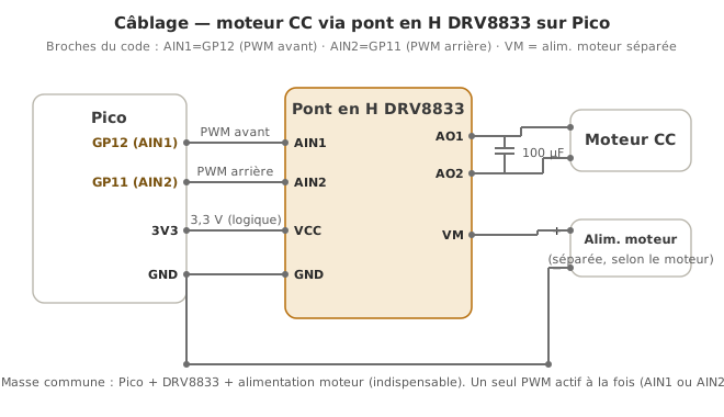
2. Wire it (DRV8833, one motor)
| DRV8833 | Pico |
|---|---|
AIN1 | GP12 (direction 1) |
AIN2 | GP11 (direction 2) |
AO1, AO2 | motor terminals |
VCC (logic) | 3.3 V |
VM (power) | motor supply (depending on the motor) |
GND | supply GND plus Pico GND (common) |
The DRV8833 expects two signals per motor: you vary the speed by sending a PWM onto AIN1 (forward) or AIN2 (reverse), the other being at 0.
3. Power it
A separate motor supply as soon as the motor draws more than ~50 mA: a battery or pack suited to the motor, a LiPo, or a bench supply. Common GND between the Pico and the motor supply. A 100 µF capacitor near the motor terminals absorbs the peaks.
4. Write the code
from machine import Pin, PWM
from time import sleep

av = PWM(Pin(12)); av.freq(1000)     # AIN1: forward
ar = PWM(Pin(11)); ar.freq(1000)     # AIN2: reverse

def avancer(vitesse):                # speed 0..65535
    ar.duty_u16(0)
    av.duty_u16(vitesse)

def reculer(vitesse):
    av.duty_u16(0)
    ar.duty_u16(vitesse)

def arret():
    av.duty_u16(0)
    ar.duty_u16(0)

while True:
    avancer(30000); sleep(2)
    arret();        sleep(0.5)
    reculer(50000); sleep(2)
    arret();        sleep(0.5)
The motor turns one way, stops, sets off the other way. (On an L298N you would keep 2 direction Pin plus 1 PWM on ENA. The principle is the same.)
Example — Speed on a potentiometer plus a direction button
A MicroPython elegance: read_u16() and duty_u16() are both 16 bits → the potentiometer’s speed drives the PWM with no scaling.
Wiring: DRV8833 as in step 2; potentiometer on GP26 (→ micropython-capteur-analogique-en); button between GP14 and GND (PULL_UP, no external resistor).
from machine import Pin, PWM, ADC
from time import ticks_ms, ticks_diff

av = PWM(Pin(12)); av.freq(1000)
ar = PWM(Pin(11)); ar.freq(1000)
pot = ADC(Pin(26))
bouton = Pin(14, Pin.IN, Pin.PULL_UP)

sens_avant = True
etat_stable, dernier_btn = 1, 1
dernier_chg = ticks_ms()

while True:
    vitesse = pot.read_u16()              # 0..65535, usable as is

    lect = bouton.value()                 # debouncing + edge
    if lect != dernier_btn:
        dernier_chg = ticks_ms(); dernier_btn = lect
    if ticks_diff(ticks_ms(), dernier_chg) > 30 and lect != etat_stable:
        etat_stable = lect
        if etat_stable == 0:
            sens_avant = not sens_avant

    if sens_avant:
        ar.duty_u16(0); av.duty_u16(vitesse)
    else:
        av.duty_u16(0); ar.duty_u16(vitesse)
How to read this code
The non-blocking debouncing rests on two variables:
dernier_btnholds the last raw reading (to restart the stopwatch as soon as the signal moves),etat_stableholds the confirmed state (kept once the signal has been stable for 30 ms). The direction only flips on a falling edge (etat_stable == 0): withPULL_UP, the pin sits at 1 at rest and drops to 0 when pressed — one flip per press. Everything is non-blocking: nosleep(), the motor stays driven on every pass.
Pitfalls
3.3 V logic on an L298N. The L298N’s inputs are meant for 5 V: 3.3 V may be read badly. On the Pico, prefer the DRV8833 or TB6612 (3.3 V inputs). A pitfall specific to 3.3 V boards.
The Pico reboots when the motor starts. A current peak causes a voltage drop. A separate supply for the motor, a 100 µF capacitor across its terminals.
No common GND. Direction signals with no reference → the bridge flips at random. Always a common GND.
Instant reversal of direction. Switching brutally from one direction to the other (with no arret() in between) causes a violent reverse current. Good practice: arret() plus a short pause before the reversal.
Two PWM high at the same time. Setting AIN1 and AIN2 above 0 = braking or an internal short circuit. Drive only one at a time (the other at 0).
Motor stalled (rotor blocked). The motor draws full current (5-10× the nominal) without turning, and heats up. Detect it (current measurement, rotation sensor) and cut it.
PWM too low, motor audible. A PWM frequency in the audible band makes the motor whine. Set freq() (often 1-20 kHz) to suit the motor.
Special case — Closed loop with an encoder
A bare DC motor has no feedback: the real speed depends on the supply, the load, the wear. For accurate control: an encoder on the shaft (read through interrupts) plus PID control on the measured speed (see PID control). That is the natural evolution of a robot that has to follow a repeatable path.
Where it fits in the project
- Step 2 of the proof of concept phase — motor plus driver validated on an isolated bench (rotation, direction, speed range).
- Step 3 of the proof of concept phase — integration into the measure → decide → move chain.
- Step 4 of the concept phase — choosing between DC motor, stepper and servo according to the need.
A 2-wheeled robot plus a DRV8833 plus 2 DC motors is one of the most instructive school proofs of concept: GPIO, PWM, separate supply and debouncing in a single project.
See also
- MicroPython — the module hub
- Driving a PWM output — prerequisite (speed, frequency)
- Servo · Stepper motor — the alternatives
- Interrupts — reading an encoder in closed loop
- PID control — controlling the speed
- Reading a datasheet — sizing driver and supply
- Driving a DC motor (Arduino) — the C++ equivalent