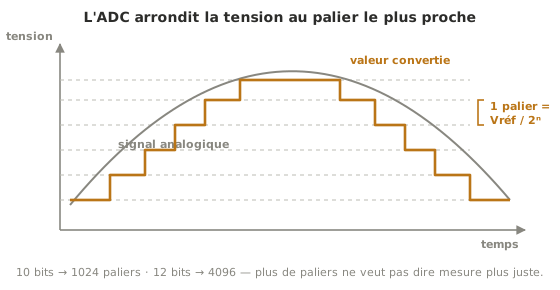
An ADC (Analog-to-Digital Converter) is the peripheral that turns an analog voltage into a number the program can work with, for instance the voltage a temperature sensor or a potentiometer delivers. Its resolution, in bits, sets how fine the measurement is: the higher it goes, the more voltage steps can be told apart.
What is it for?
Without an ADC, a microcontroller senses nothing but on or off on its logic pins. The ADC is what gives it access to the continuous quantities of the real world. Every analog sensor reading goes through it.
In practice
The conversion refers the voltage read to the reference voltage (full scale, often the supply: 5 V on an Uno, 3.3 V on an ESP32) and cuts it into 2ⁿ steps: 10 bits gives 1024 values (one step ≈ 5 mV on 5 V), 12 bits gives 4096. Two pitfalls here. Going past full scale: beyond the reference the reading saturates, and a 5 V sensor wired to a 3.3 V ADC threatens the pin itself (→ concept page Logic levels). Confusing resolution with accuracy: more steps does not mean a truer measurement. The ESP32’s 12-bit ADC, notoriously non-linear, is the illustration (→ concept page Accuracy, trueness, precision). Reading one in practice: Reading an analog sensor for Arduino, Reading an analog sensor for MicroPython.
See also
- Microcontroller — the chip that carries the ADC
- Analog sensor (Arduino) — analog reading in practice
- Analog sensor (MicroPython) — the same mechanics for MicroPython
- Input and output — the family of peripherals the ADC belongs to
- Filtering measurements — damping the noise on a converted reading, and what it costs in responsiveness
- DAC — the converter the other way round: producing a real analog voltage
- PWM — the output counterpart: metering a command rather than reading a measurement
- Measurement accuracy — resolution, trueness, precision: not to be confused