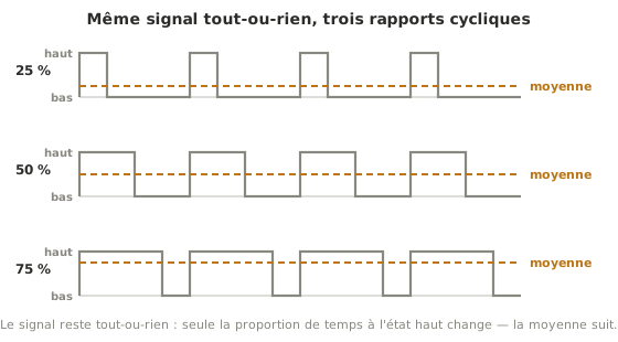
PWM (Pulse Width Modulation) is a signal that is only ever fully on or fully off, and whose proportion of time spent high is what gets varied. That proportion is called the duty cycle. On average, this switching mimics an adjustable voltage without a single analog component.
What is it for?
This is the usual way, from a microcontroller, to set a motor speed, an LED brightness or the position of a servo: you act on the duty cycle rather than on a genuinely variable voltage. The signal stays digital, and so is simple to generate on a pin.
In practice
PWM has two independent settings: the duty cycle, which meters, and the switching frequency, which says how fast the signal alternates. The frequency is chosen to suit the load. Too slow and an LED flickers. Below ≈ 20 kHz a motor whines in the audible range. A servo, for its part, expects a 50 Hz signal where only the pulse width counts. And when what is needed is a real analog voltage rather than a switched average, filtered PWM (a simple RC filter) stands in for a DAC. Putting it to work: Driving a PWM output for Arduino, Driving a PWM output for MicroPython.
See also
- Microcontroller — the chip that generates the PWM
- PWM output (Arduino) — putting it to work
- PWM output (MicroPython) — the same mechanics for MicroPython
- Timer — inside the microcontroller, this is what produces the PWM signal and sets its frequency
- Input and output — the family of peripherals PWM belongs to
- ADC — the input counterpart: reading a measurement rather than metering a command
- DAC — the real analog voltage, for when a switched average will not do
- Timing diagram — the representation that shows PWM as it actually is