Wokwi (wokwi.com) is an online simulator for microcontroller boards — Arduino, ESP32, Raspberry Pi Pico, STM32 — with a large catalogue of sensors, displays and modules. You write the code and simulate the circuit together, with no hardware at all: the LED blinks, the sensor returns a value, the serial monitor scrolls, and all of it in the browser. It is the companion to Tinkercad, richer in parts and in boards, notably the ESP32 and wireless, where Tinkercad stops at the Arduino world. Boards in the XIAO form factor (C3, S3, C6) are there too: they carry the same SoC as the boards of the ESP32 module, so the code transfers as it stands, and only the pinout changes. This page is a tool tutorial belonging to the circuit simulation hub.
What is it for?
Wokwi is there to check a microcontroller circuit before the hardware:
- test the code on the simulated circuit — check that a program really does read a sensor or drive an actuator, without waiting for the board or risking a part.
- prototype ESP32 and wireless work. Wokwi simulates the ESP32 and some Wi-Fi scenarios, which are out of Tinkercad’s reach.
- simulate in MicroPython. The Pico and the ESP32 can also be programmed in MicroPython or CircuitPython, not only in C++: it is the simulator the MicroPython module settles on, see simulating a Pico.
- share with a single link. A Wokwi project goes out as a URL, which is handy for asking for help or for showing a circuit to the team.
It is a proof of concept tool: it validates the logic of the program and of the wiring. It does not spare you the pass on real hardware (see Pitfalls).
Getting started
We run through a first complete project here (an ESP32 that says hello over the serial link) so as to install the moves of the tool before wiring anything at all.
1. Choose a board
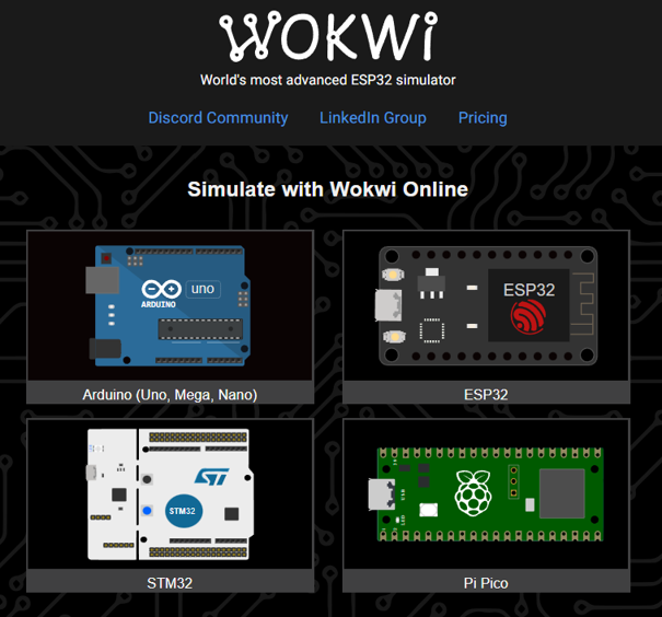
The wokwi.com home page offers four families: Arduino (Uno, Mega, Nano), ESP32, STM32 and Pi Pico. Take the ESP32.
2. Choose a starter template
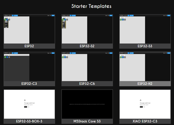
Wokwi then offers starter templates: an empty project for each chip variant (ESP32, S2, S3, C3, C6, H2) and a few ready-made boards, among them the XIAO ESP32-C3, which incidentally proves that the XIAO form factor really is simulated. To begin with, the empty ESP32 template is enough.
3. Write the code
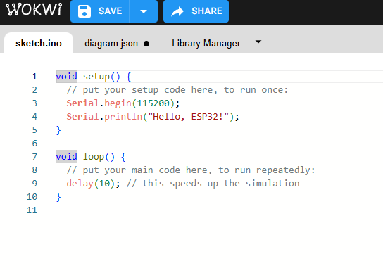
The editor opens sketch.ino (the same file as an Arduino sketch) with, beside it, the diagram.json tab that describes the wiring and a Library Manager for the libraries.
void setup() {
  Serial.begin(115200);              // opens the serial link at 115 200 baud
  Serial.println("Hello, ESP32!");   // sends the message once, at start-up
}

void loop() {
  delay(10);                         // nothing to do here: the pause eases the simulation
}
4. Look at the schematic
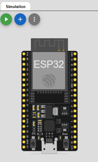
For the moment the schematic area holds nothing but the board: this program drives no pin at all, it speaks only over the simulated USB.
5. Run the simulation
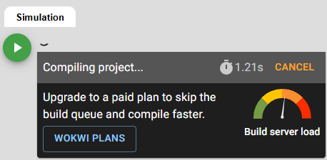
The run button compiles, then executes. Two outcomes: the build succeeds and the board starts, or it fails, and the message then points at the offending line, exactly as in the Arduino IDE (see reading compiler errors).
6. Read the serial monitor
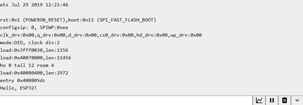
The message appears, preceded by the boot log of the chip, those rst:0x1, mode:DIO, load:0x... lines the ESP32 spits out at every reset. It is not an error: it is the bootloader talking, and it is the bootloader that imposes the 115 200 rate (see the ESP32 Arduino core).
Wokwi also carries a virtual logic analyzer: you put your channels on the wires of a simulated bus, you capture, and you read the frames back as you would with a real logic analyzer — enough to check an I²C or UART exchange before anything has been wired at all.
Example — Blinking an LED
The previous program touched no pin. We now add a real circuit: the blinking LED, first reflex of every start on a microcontroller.
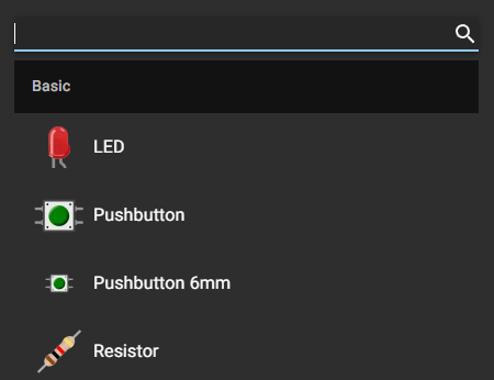
- Add the parts. The
+button of the schematic area opens the catalogue: take an LED and a resistor from it.
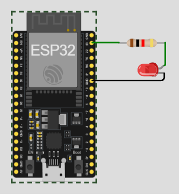
- Wire it. GPIO23 goes to the resistor, the resistor to the anode of the LED, and the cathode comes back to the GND of the board. This is the circuit you would build identically on real hardware — to find out which pins are free and which to avoid, see configuring the GPIO.
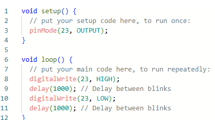
- Write the code. The program needs only two moves: declare the pin as an output, then alternate the two levels.
void setup() {
  pinMode(23, OUTPUT);       // pin 23 becomes an output
}

void loop() {
  digitalWrite(23, HIGH);    // turns the LED on
  delay(1000);               // waits one second
  digitalWrite(23, LOW);     // turns the LED off
  delay(1000);               // waits one second
}
- Run it and compare with what you expected. The LED should light for one second and go out for one second. If it stays dark, it is the wiring — pin number, direction of the LED, or a forgotten ground. If the rhythm is wrong, it is the
delay. The diagnosis is made without touching the hardware, and the reasoning is the same as on the bench.
What Wokwi brings: you validate the code (C++) and the circuit together before soldering or ordering anything at all. What follows — reading an analog sensor, driving a PWM output, talking on a bus — is prototyped the same way, by taking up the circuits of the ESP32 module.
Pitfalls
Simulation ≠ reality. Wokwi simulates the logic, not the electrical detail: real currents, rise times, button bounce or sensor noise are not all reproduced. A circuit that works under Wokwi still has to be checked on hardware.
Believing every part is available. The catalogue is broad but not exhaustive: an exotic sensor may be missing, or only partly modelled. Check that the key part of the project really is simulated before building everything on top of it.
Neglecting real constraints. The simulator sometimes lets through a wiring that real hardware would not forgive — typically a 5 V signal on a 3.3 V ESP32 pin. Wire in Wokwi as you would wire for real.
Forgetting the pass on hardware. Wokwi saves time upstream, but the code will still have to be uploaded and re-checked on the physical board: this is a proof-of-concept step, not the end of the road.
See also
- Circuit simulation — the hub: method and reading of results
- Tinkercad — the equivalent on the beginner Arduino side, with no ESP32
- ESP32 — the family Wokwi simulates, wireless included
- XIAO ESP32-S3 — same SoC, simulated too (C3, S3, C6 variants)
- Configuring ESP32 GPIO — which pins are free, which to avoid; same question on the Arduino side and on the MicroPython side
- Simulating a Pico in MicroPython — the same tool, on the MicroPython side
- Logic analyzer — the hardware counterpart of Wokwi’s virtual analyzer
- C++ — writing the code the simulation runs
- Logic levels — respecting 3.3 V / 5 V, even in simulation