Tinkercad Circuits is an electronic circuit simulator available free of charge in the browser (tinkercad.com). It lets you build an Arduino circuit, write the code, and simulate how it behaves without any physical hardware. It is the ideal way in before your board arrives, and a risk-free sandbox for trying a setup out before putting a real component in danger.
What is it for?
Tinkercad solves three problems that come up all the time in a school project:
- Getting started with no hardware — when the board has not been ordered yet, or while you wait for the lab session, you can still write and test your code.
- Trying a risky wiring job out before you build it — miswiring a motor, an H-bridge or a supply can destroy a component in an instant. Simulating it costs nothing.
- Sharing easily — a Tinkercad project is shared through a URL, with no file to send (handy for showing a setup to a supervisor, or asking for help remotely).
The tool has its limits: not every component is simulated, the timing is not realistic down to the microsecond, and some modules (specialised sensors, complex displays) are missing. Tinkercad does not replace the real build. It speeds up the ideas stage and makes the first power-up safer.
The general method of simulation (choosing the analysis that fits the question, placing the probes, checking the result against an expected order of magnitude) and the survey of the other simulators are covered by the circuit simulation hub.
Step by step
Four steps: open a project, place the components, write the code, simulate.
1. Create an account and open a new circuit
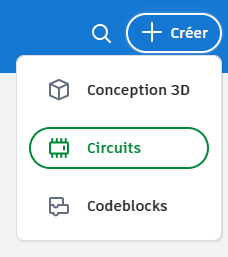
Go to tinkercad.com and create a free account (a Google account or an Autodesk Education institutional account works too). From the dashboard, click Créer → Circuit (Create → Circuit). An empty workplane opens.
2. Place the components
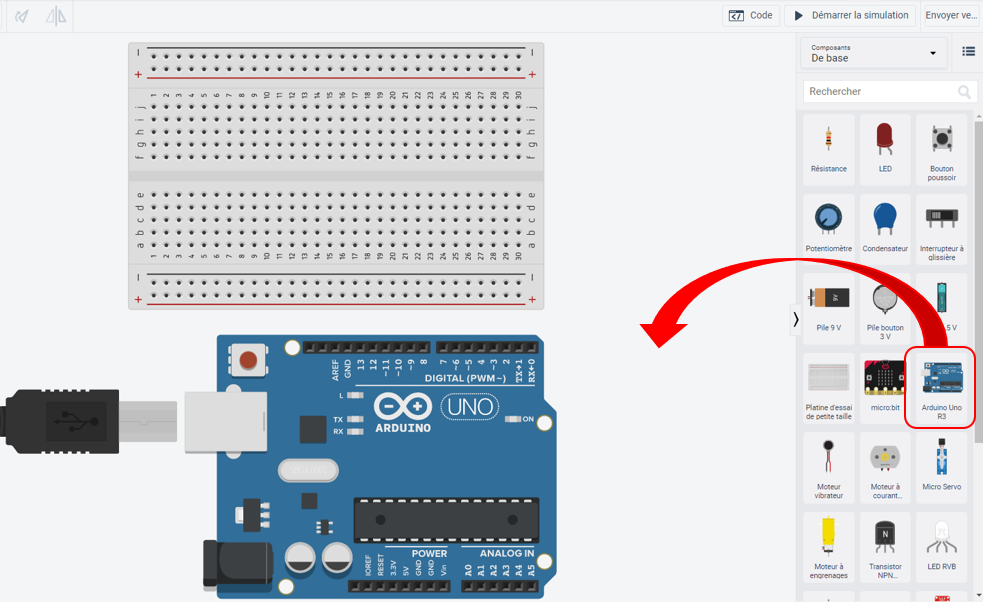
To the right of the workplane, a component sidebar holds every part available: Arduino Uno, breadboard, resistors, LEDs, sensors, modules and so on. Filter by category (De base / Tous, that is Basic / All) or search by keyword (“Arduino”, “LED”, “DHT”).
Drag and drop the components onto the workplane. Right-click to rotate a part. To wire, click on a pin: a wire starts, follow it by clicking at each bend, and finish with a click on the target pin. Values (resistance, voltage) are set by clicking the component and editing the panel that appears.
3. Write the code
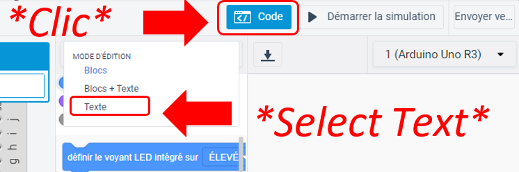
Click Code at the top right. Two modes are available:
- Blocs (Blocks) — Scratch-style visual programming: you assemble instructions with the mouse, with no syntax to write. It suits discovery at school level, but this mode has no place in professional work. We do not use it here.
- Texte (Text) — the classic Arduino C++ editor. This is the mode to use from the start: it is exactly the code you will find again on the real board and in industry.
Above the editor, a button switches between the two modes. Tinkercad generates the C++ code matching the block build when you go from graphics to text, useful once to see how they correspond, but you then stay in Texte mode (going back to blocks wipes out the edited code, see Pitfalls).
4. Start the simulation and watch
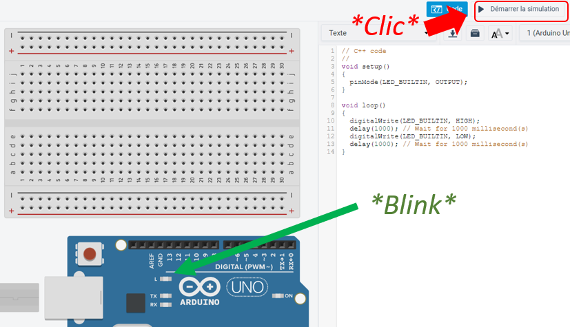
Click Démarrer la simulation (Start Simulation). Tinkercad virtually uploads the code into the simulated Arduino. LEDs light up, motors turn, displays show things (according to the code and the wiring).
A Moniteur série (Serial Monitor) button, at the bottom of the code panel, shows the Serial.print() output as it runs, just as in the real IDE (see serial monitor).
To stop, click Arrêter la simulation (Stop Simulation). You can change the code or the wiring on the fly, then start again.
Example — Blink simulated with a button
The Blink sketch again, but triggered by an external pushbutton, to show how Tinkercad handles a digital input as well as an output.
Wiring: LED on pin 13 through a 220 Ω resistor to GND; button between pin 2 and GND, set to INPUT_PULLUP (no external pull-up resistor needed, the internal one is enough).
const int LED = 13;
const int BOUTON = 2;

void setup() {
  pinMode(LED, OUTPUT);
  pinMode(BOUTON, INPUT_PULLUP);
}

void loop() {
  if (digitalRead(BOUTON) == LOW) {   // button pressed (pull-up inverts it)
    digitalWrite(LED, HIGH);
  } else {
    digitalWrite(LED, LOW);
  }
}
Start the simulation and click the button on the workplane: the LED stays lit as long as it is held. If the wiring is wrong (say the button between 5 V and the pin instead of GND), the LED never lights, however long you press. The pin stays pulled HIGH by the pull-up, and the simulation reproduces the mistake faithfully without breaking anything.
Pitfalls
“It works in Tinkercad” ≠ “it works for real”. Tinkercad simulates an idealised model: no noise, no contact bounce, no realistic voltage drops, approximate timing. Software debouncing can look pointless in simulation and turn out to be essential on the real button. Validating in simulation is a stage, not the last one.
Missing components. Many real off-the-shelf sensors (DHT22, MPU6050, the ACS712 current sensor, wireless modules) are not in the Tinkercad library. Check what is available before basing a simulated proof of concept on it.
Timing you cannot trust. The millis() and micros() functions, and any timing-critical code, do not behave as they do on hardware. Do not build a frequency measurement or a timed control loop on them without checking on real hardware.
No realistic PWM. analogWrite() is rendered graphically (the LED changes brightness), but the virtual oscilloscope and fine measurement are no match for a real scope on a modulated square wave.
Blocks to text is a one-way switch. Going from blocks to text generates the matching C++, but the reverse is not true. Once the code has been edited as text, going back to block mode wipes out the changes. Switch to text early, and never go back to blocks.
Autosave with a lag. Tinkercad saves continuously, but after a network or session drop the last few seconds can be lost. For anything important, export the code regularly (Code → Télécharger le code, that is Code → Download Code).
An internet connection is required. The tool is 100% online. With no network, no Tinkercad. For offline use, Wokwi (another web tool) or a locally installed simulator are the fallbacks.
Special case — Wokwi for the ESP32 and more advanced microcontrollers
Tinkercad handles the Arduino Uno and Mega well, along with a few standard components. To simulate an ESP32 (Wi-Fi, BLE, an SSD1306 display, driving advanced modules), have a look at Wokwi (wokwi.com), a complementary web simulator that covers a far wider range of boards and modules. Same way of working, similar interface.
Where it fits in the project
- Step 1 of the proof-of-concept phase — Tinkercad is there to prototype the wiring and the logic quickly, before the first lab session. You turn up with a sketch already checked in simulation, and you gain on the first real power-up.
- Step 2 of the proof-of-concept phase — when a sensor or a module does not work for real, simulating the same wiring separately in Tinkercad tells a logic problem from a hardware one.
- Demonstrating and teaching — the simulation can be projected and shared through a URL, which makes it an excellent way to explain a piece of logic without touching any hardware.
Half an hour of simulation before the real circuit is first powered up cuts down the risk of frying a component through a bad first wiring job, which is a very good trade.
Going further
- tinkercad.com — the tool itself.
- wokwi.com — the alternative simulator, with wider coverage (ESP32, STM32, Raspberry Pi Pico).
- Tinkercad Learning Center — the official guided tutorials.
See also
- Arduino — hub for the Arduino tutorials
- Getting started with Arduino — the same thing on real hardware
- Circuit simulation — the method hub: choosing an analysis, reading and checking the results
- Wokwi — a richer MCU board simulator (ESP32, wireless)
- Arduino serial monitor — also available inside Tinkercad
- Microcontroller — a survey of the MCU families