The GPIO (General Purpose Input/Output) pins of an Arduino board are the digital pins you can configure as inputs or outputs, to read or send a binary signal (0 V / 5 V on the Uno R3). Configuring a GPIO correctly is the basic move of every embedded program. Forgetting pinMode(), mixing the modes up or ignoring the floating state of an input is the most frequent cause of unpredictable behaviour at the start of a project.
What is it for?
Every binary sensor and actuator (button, limit switch, LED, relay, buzzer, presence sensor) goes through the GPIO. Three modes cover ~80% of Arduino builds: INPUT (floating input), INPUT_PULLUP (input pulled high by an internal resistor), OUTPUT (output driven to HIGH or LOW). Understanding those three modes and the wiring that goes with them makes most of the other Arduino tutorials readable.
Step by step
Four steps: identify the pin, set the mode, read or write, check the wiring.
1. Identify the digital pins
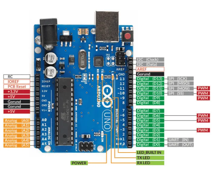
On the Arduino Uno, pins D0 to D13 are digital GPIO. D0 and D1 are also used by USB (TX/RX), so keep them clear for anything else. Pins A0 to A5 can serve as digital GPIO too (referred to as A0, A1, …, or as 14, 15, …, 19).
On the Mega 2560: D0 to D53. On the Nano: D0 to D13 plus A0-A7 (D0/D1 shared with USB as on the Uno, A6/A7 only work as analog inputs).
2. Set the mode in setup()
One pinMode() line per pin used:
const int LED = 13;
const int BOUTON = 2;

void setup() {
  pinMode(LED, OUTPUT);
  pinMode(BOUTON, INPUT_PULLUP);
}OUTPUT— the pin drives a signal out to the world (LED, relay, transistor).INPUT— the pin reads an outside signal with no internal biasing at all. If nothing is wired to it, the reading is random (50 Hz noise picked up by the aerial the wire makes). Only use it if an external resistor holds the input at a known level.INPUT_PULLUP— the pin reads a signal, but an internal resistor of roughly 20 to 50 kΩ pulls the potential towards+5 V. Inverted logic: the pin readsHIGHat rest,LOWwhen you connect it to GND (typically through a button).
3. Read or write in loop()
void loop() {
  int etat = digitalRead(BOUTON);  // HIGH or LOW
  if (etat == LOW) {                // button pressed (inverted pull-up logic)
    digitalWrite(LED, HIGH);
  } else {
    digitalWrite(LED, LOW);
  }
}
digitalRead() returns HIGH or LOW. digitalWrite() takes the same constants (or 1 / 0).
4. Wire it properly
- Driving an LED: a series resistor of 220 Ω to 1 kΩ between the pin and the anode (+) of the LED, cathode (-) to GND. With no resistor, the LED burns out or the pin is damaged.
- Reading a button,
INPUT_PULLUPmode: one side of the button to the pin, the other side to GND. Nothing else. - Reading a button,
INPUTmode: you need an external resistor (pull-up to+5 Vor pull-down to GND, ~10 kΩ) to give it a defined rest state.
Example — A button that lights an LED
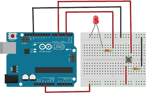
Wiring and full code to validate the pinMode + digitalRead + digitalWrite chain.
Wiring:
- LED anode (+) → 220 Ω resistor → pin D13.
- LED cathode (-) → GND.
- Button between pin D2 and GND (
INPUT_PULLUPconfiguration, no external resistor).
const int LED = 13;
const int BOUTON = 2;

void setup() {
  pinMode(LED, OUTPUT);
  pinMode(BOUTON, INPUT_PULLUP);
}

void loop() {
  if (digitalRead(BOUTON) == LOW) {
    digitalWrite(LED, HIGH);
  } else {
    digitalWrite(LED, LOW);
  }
}
Upload, then press the button: the LED lights. Release it: it goes out. If the LED stays lit all the time (as though the button were permanently pressed), the pin is tied to GND continuously, often a four-pin tactile button wired on the wrong pair: two of its pins are already joined inside and tie the pin to GND permanently. The pull-up then loses the battle against that solid connection.
Pitfalls
pinMode() forgotten. A pin left unconfigured behaves in an undefined way (default state varies from board to board). Symptom: the code looks right but nothing happens.
Confusing INPUT and INPUT_PULLUP. In INPUT with no external resistor, the pin floats, a random reading that can look as though it responds to the touch of a hand (the body acts as a 50 Hz aerial). In INPUT_PULLUP, the pin has a defined rest state. That is almost always the right choice for a button.
Inverted pull-up logic. A button in INPUT_PULLUP reads LOW when pressed. A test such as if (digitalRead(BOUTON) == HIGH) will light the LED when the button is released, the opposite of what you meant.
LED wired with no resistor. A red LED draws ~20 mA at 2 V. Wired straight between 5 V and GND, it draws an excessive current that burns it out (or damages the pin). Always a series resistor, worked out from the LED’s forward voltage (220 Ω to 1 kΩ for a standard LED on 5 V).
Maximum current exceeded. Each pin takes 20 mA in normal use (40 mA absolute, destruction beyond that). The total across all the pins of an ATmega328P must stay under ~200 mA. To drive anything hungrier (relay, motor, LED strip), go through a transistor or a dedicated module.
digitalRead() on a pin set to OUTPUT. Possible but pointless. You read back the state you have just written. Probably the sign of a badly configured mode.
Unused floating pin. A pin declared INPUT with nothing wired to it picks up noise. Read it, and you get randomness. For unused pins you may want to read one day, either INPUT_PULLUP, or an external pull to a defined level.
Special case — PWM, ADC and bus pins
Not all digital pins are equivalent:
- PWM — on the Uno, D3, D5, D6, D9, D10, D11 (marked
~) generate a PWM signal withanalogWrite()(see driving a PWM output). - ADC — A0 to A5 are the analog inputs (
analogRead), with a GPIO role as an alternative. - Bus — D0/D1 (UART), A4/A5 (I2C), D10-D13 (SPI). Using a pin as GPIO makes it unavailable for its dedicated bus.
The official pinout of your board is the reference. Keep it within reach.
Where it fits in the project
- Step 2 of the proof of concept phase — first individual input and output trials (button, LED, limit switch) before assembling anything.
- Step 2 of the integration and testing phase — piece-by-piece validation of the I/O before the pyramid of tests.
Mastering the three GPIO modes on a small isolated build is the foundation almost every Arduino tutorial that follows rests on. No point moving on to sensors or actuators before that groundwork is solid.
See also
- Arduino — hub of the Arduino tutorials
- GPIO — the cross-cutting concept page (modes, state at boot, GPIO in the other families)
- off input — the natural next step (button with debouncing)
- off output — output beyond the LED (relay)
- GPIO state at power-up — sensitive pins before
setup()runs - Logic levels — 3.3 V against 5 V, sensor compatibility