An on/off output switches a load between two states: powered or off. Indicator LED, buzzer, power relay, fan on a transistor: all these loads are driven with digitalWrite(). This page covers the three cases met on a school project: driving a small load straight from the pin (LED), driving a medium load through a transistor (buzzer, fan), driving a mains or a large inductive load through a relay module.
What is it for?
Every binary command to an actuator — lighting an indicator, tripping a valve, starting a fan, switching a mains circuit — goes through an on/off output. Choosing the right interface (pin direct, transistor, relay module) depends on two quantities: the current the load draws, and the supply voltage of the load. The rule of thumb to remember: 20 mA and 5 V maximum straight from a pin on an Arduino Uno. Beyond that, you put a buffer component in between.
Step by step
Four steps: choose the interface, wire it, write the code, check the consumption.
1. Choose the interface to suit the load
| Load | Voltage | Current | Interface |
|---|---|---|---|
| Standard LED | 1.8-3.3 V | 5-20 mA | Pin direct plus series resistor |
| Passive buzzer, small 5 V relay | 5 V | 20-100 mA | NPN transistor (2N2222, BC547) or MOSFET (2N7000) |
| 5 V relay module (with opto) | 5 V logic | < 20 mA on the logic side | Pin direct (the module handles the load) |
| 12 V fan, motor, mains lamp | > 5 V | > 100 mA | Relay module or H-bridge, never on a pin |
For the rest of the procedure, take the three usual cases: LED (pin direct), buzzer (transistor), relay module (pin direct to the module).
2. Wire it
LED: anode (long leg, +) → 220 Ω to 1 kΩ resistor → pin D8; cathode (short leg, −) → GND.
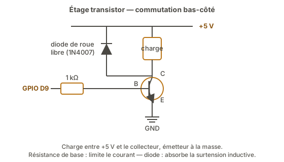
Buzzer through an NPN 2N2222 transistor: emitter → GND; collector → buzzer − terminal; buzzer + terminal → +5 V; base → 1 kΩ resistor → pin D9. (The resistor limits the base current.)
5 V relay module: the module’s IN pin → pin D10; the module’s VCC → Arduino +5 V; the module’s GND → Arduino GND. The mains load goes on the module’s COM and NO terminals, and the Arduino never touches it.

3. Write the code
The code is the same whatever the interface: digitalWrite() does not know whether it is driving an LED or a relay module.
const int LED    = 8;          // LED on D8 (pin direct)
const int BUZZER = 9;          // buzzer through a transistor on D9
const int RELAIS = 10;         // relay module on D10

void setup() {
  pinMode(LED,    OUTPUT);      // all three pins as outputs
  pinMode(BUZZER, OUTPUT);
  pinMode(RELAIS, OUTPUT);
}

void loop() {
  digitalWrite(LED,    HIGH);   // LED lit
  digitalWrite(BUZZER, HIGH);   // buzzer on
  digitalWrite(RELAIS, HIGH);   // relay pulled in (HIGH or LOW depending on the module, see the warning)
  delay(2000);                  // hold for 2 s
  digitalWrite(LED,    LOW);    // switch everything off
  digitalWrite(BUZZER, LOW);
  digitalWrite(RELAIS, LOW);
  delay(2000);                  // 2 s off, then start again
}
Warning
Relay logic is often inverted. Plenty of cheap 5 V relay modules (LU-5V, JQC-3FF) are active low:
digitalWrite(RELAIS, LOW)pulls the relay in,HIGHreleases it. Check on the module or by trying it: the red LED on the module lights when the relay is pulled in.
4. Check the consumption
Before pressing Upload on a new build, add it up in your head:
- How many mA does each direct load draw?
- How many mA does that make in total on the board?
- Is the USB supply (500 mA at most from a computer) enough?
An Arduino that restarts at regular intervals as soon as you switch an actuator on is nearly always under-powered. The fix: an external supply on Vin (7-12 V) or on the barrel jack, or a separate supply for the loads.
Example — Buzzer alarm plus flashing LED
A typical case: raising a visual and audible alarm on an event (simulated here by a timer).
const int LED    = 8;
const int BUZZER = 9;

void setup() {
  pinMode(LED,    OUTPUT);
  pinMode(BUZZER, OUTPUT);
}

void loop() {
  // one burst = 3 short beeps, LED flashing at the same time
  for (int i = 0; i < 3; i++) {   // repeat 3 times
    digitalWrite(LED,    HIGH);   // LED and buzzer ON
    digitalWrite(BUZZER, HIGH);
    delay(200);                   // ON for 200 ms
    digitalWrite(LED,    LOW);    // LED and buzzer OFF
    digitalWrite(BUZZER, LOW);
    delay(200);                   // OFF for 200 ms
  }
  delay(3000);  // pause before the next burst
}
The code would have the same shape to drive a relay module instead of the buzzer: only the hardware interface changes.
Pitfalls
Load draws more than 20 mA per pin. Symptom: the output cannot hold its voltage, the pin heats up, sometimes the Arduino restarts. Always measure (or estimate high) the nominal current of the load before wiring it straight to a pin.
LED with no resistor. The LED burns out, or the pin is damaged. Always 220 Ω to 1 kΩ in series for a standard LED on 5 V.
Active buzzer against passive buzzer. An active buzzer (with a built-in oscillator) sounds as soon as you apply its nominal voltage: digitalWrite(BUZZER, HIGH) is enough. A passive buzzer (a bare piezo transducer) does not sound on an on/off output. It needs a square wave (see tone() or PWM).
Inductive load with no flyback diode. Relay coil, motor, solenoid valve: cutting the current produces an overvoltage that can destroy the switching transistor. A 1N4007 diode, reversed, across the coil absorbs that overvoltage. Commercial relay modules already include one.
Relay module powered from the Arduino 5 V plus a big load. A standard relay module draws ~70 mA when it pulls in. Several modules plus the Arduino plus other loads → you quickly go past 200 mA in total. An external supply for the module as soon as there is more than one.
Forgetting the relay module’s inverted logic. The code seems to work backwards, the relay pulls in when you set it to LOW. That is deliberate: the module’s optocoupler inverts the logic. Read the module’s documentation or test it.
An on/off output for a DC motor. A motor wants a direction (forwards/backwards) and a speed: it needs an H-bridge, not an on/off output (see driving a DC motor). An on/off output on a motor only runs it at full speed in one direction.
Special case — 230 V mains loads
Driving mains loads (a lighting lamp, a 230 V solenoid valve, a pump) is never done directly — always through a relay module or a solid-state relay (SSR). Three points to watch:
- Galvanic isolation between the 5 V logic and the mains: only modules with an optocoupler on the input guarantee it (
PC817,EL817). - Contact rating: a low-end relay is rated around 10 A at 250 V — enough for a lamp or a domestic pump, not enough for a heater.
- Electrical safety: any 230 V wiring on a school project is done under supervision, with an upstream breaker and mechanical protection of the bare terminals.
Where it fits in the project
- Step 2 of the proof of concept phase — every binary actuator (indicator LED, alarm buzzer, relay powering a subsystem) is validated on/off before being integrated into the control loop.
- Step 2 of the integration and testing phase — piece-by-piece validation before the pyramid of tests.
Choosing the interface (pin direct / transistor / relay module) before writing the command, from the components’ datasheets (and not after burning the first one) makes the difference between a PoC that converges and one that drags on with hybrid hardware-and-software bugs.
See also
- Arduino — hub of the Arduino tutorials
- Configuring Arduino GPIO — prerequisite (OUTPUT mode, maximum currents)
- off input — the matching input
- Driving a PWM output — to vary the brightness of an LED or the speed of a motor
- Driving a DC motor — an H-bridge for a motor that needs a direction
- Reading a datasheet — to check the currents and voltages of the modules