Programming a state machine on Arduino means turning a diagram of states and transitions into C++ using the switch(etat) pattern: one variable holds the current state, and the loop() runs the matching block on every pass. Coupled with non-blocking timing (millis()), the pattern drives sequential behaviour — traffic lights, a gate, a machine cycle — without ever freezing the program with delay().
What is it for?
As soon as an Arduino setup has to run through phases (“green, then amber, then red”, “open, wait, close”), two traps await the beginner: piling up delay() calls that leave the board deaf to the rest of the world while it waits, or multiplying boolean flags until nothing is readable. The switch(etat) pattern settles both:
- it structures the code into one clear block per state, mirroring the diagram;
- it keeps the loop responsive: between two state changes, the Arduino goes on reading its inputs;
- it makes the transitions explicit, and therefore easy to reread and to test.
It is the skeleton of almost any program that has to control something. It goes in during the proof of concept, at the point where you code the behaviour of a function.
Step by step
Four steps: list the states, structure the loop, code the timed transitions, then wire it up and test.
1. List the states
An enum names the states and makes them readable throughout the code. One variable holds the current state. You set it explicitly (no undefined state at start-up). A time variable will stamp the moment of entry into the current state.
enum Etat { VERT, JAUNE, ROUGE };

Etat etat = VERT;            // explicit initial state
unsigned long tDebut = 0;    // timestamp (ms) of entry into the current state
Use an enum rather than bare numbers (0, 1, 2): case VERT reads, case 0 does not.
2. Structure the loop with switch(etat)
One case per state, each ending in break. On every pass through loop(), a single block runs, the one for the current state.
void loop() {
  switch (etat) {
    case VERT:
      // 1) apply the state's outputs
      // 2) test the transitions
      break;
    case JAUNE:
      break;
    case ROUGE:
      break;
  }
}
Inside each case you do two things: reflect the state on the outputs (light the right LEDs), then test the conditions for leaving towards another state.
3. Code the transitions and the non-blocking timing
A transition is coded in two moves: change etat, then restamp the entry with tDebut = millis(). For a delay, do not block with delay(). Compare the time elapsed since entering the state instead.
case VERT:
  if (millis() - tDebut >= DUREE_VERT) {   // event: the time has elapsed
    etat = JAUNE;
    tDebut = millis();                     // stamp the entry into the new state
  }
  break;
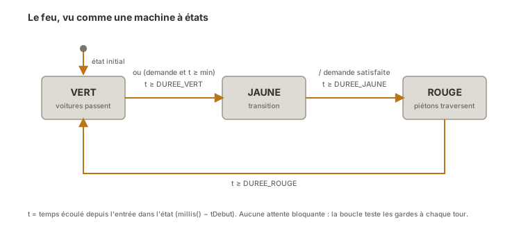
millis() returns the number of milliseconds since start-up. The subtraction millis() - tDebut gives the time spent in the state: the comparison blocks nothing, and the loop keeps running (see delay() vs millis()). A guard condition from the diagram becomes a plain combined if: if (time elapsed || (demandePieton && minimum elapsed)).
4. Wire it up and upload
For the example below: five LEDs (three for the cars, two for the pedestrians), each with its 220 Ω series resistor, and a push button between a pin and GND in INPUT_PULLUP (see off input for the debouncing).
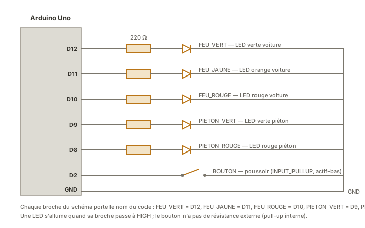
Once uploaded, the cycle runs on its own. A press on the button brings the change to red forward, to let someone cross.
Example — traffic lights with a pedestrian crossing
A single-light junction: the cars run through green → amber → red, the pedestrians have a red/green light and a request button. The button latches a request which, once a minimum of green has elapsed, triggers the change to red, exactly the [request && minimum elapsed] guard condition from the diagram.
enum Etat { VERT, JAUNE, ROUGE };

const int FEU_VERT     = 12;
const int FEU_JAUNE    = 11;
const int FEU_ROUGE    = 10;
const int PIETON_VERT  = 9;
const int PIETON_ROUGE = 8;
const int BOUTON       = 2;

const unsigned long DUREE_VERT     = 6000;  // car green (ms)
const unsigned long DUREE_VERT_MIN = 2000;  // minimum before yielding to a pedestrian
const unsigned long DUREE_JAUNE    = 2000;
const unsigned long DUREE_ROUGE    = 5000;  // pedestrian crossing time

Etat etat = VERT;
unsigned long tDebut = 0;
bool demandePieton = false;

void setup() {
  pinMode(FEU_VERT, OUTPUT);
  pinMode(FEU_JAUNE, OUTPUT);
  pinMode(FEU_ROUGE, OUTPUT);
  pinMode(PIETON_VERT, OUTPUT);
  pinMode(PIETON_ROUGE, OUTPUT);
  pinMode(BOUTON, INPUT_PULLUP);
  tDebut = millis();
}

void loop() {
  // Event: pedestrian press, latched until satisfied
  if (digitalRead(BOUTON) == LOW) {
    demandePieton = true;
  }

  switch (etat) {

    case VERT:                               // cars go, pedestrians stop
      digitalWrite(FEU_VERT, HIGH);
      digitalWrite(FEU_JAUNE, LOW);
      digitalWrite(FEU_ROUGE, LOW);
      digitalWrite(PIETON_VERT, LOW);
      digitalWrite(PIETON_ROUGE, HIGH);
      if (millis() - tDebut >= DUREE_VERT ||
          (demandePieton && millis() - tDebut >= DUREE_VERT_MIN)) {
        etat = JAUNE;
        tDebut = millis();
      }
      break;

    case JAUNE:                              // transition
      digitalWrite(FEU_VERT, LOW);
      digitalWrite(FEU_JAUNE, HIGH);
      if (millis() - tDebut >= DUREE_JAUNE) {
        etat = ROUGE;
        tDebut = millis();
        demandePieton = false;               // the request is satisfied
      }
      break;

    case ROUGE:                              // cars stop, pedestrians cross
      digitalWrite(FEU_JAUNE, LOW);
      digitalWrite(FEU_ROUGE, HIGH);
      digitalWrite(PIETON_ROUGE, LOW);
      digitalWrite(PIETON_VERT, HIGH);
      if (millis() - tDebut >= DUREE_ROUGE) {
        etat = VERT;
        tDebut = millis();
      }
      break;
  }
}
How to read this code
The key transition sits in
case VERT:if (millis() - tDebut >= DUREE_VERT || (demandePieton && millis() - tDebut >= DUREE_VERT_MIN)). It reads as “switch to amber if the green has run its full time (DUREE_VERT) or else a pedestrian has pressed (demandePieton) and the green minimum has already elapsed”. The||opens two ways out, the second guarded by a minimum so a green that has only just started is not cut short.demandePietongoestrueon the press (tested at the head ofloop(), so on every pass) and returns tofalseon enteringROUGE, once the request has been satisfied. On every state change,tDebut = millis()restamps the entry so the duration comparisons start again from zero.The precedence of
&&over||, which governs that reading, is a language mechanism rather than an embedded idiom: see reading a C++ program.
The program contains no delay() at all: the loop runs continuously, reads the button on every pass, and moves through the cycle when the conditions are met. Adding a fourth state (a night-time flashing amber, say) comes down to adding a case: the structure absorbs it without a rewrite.
To stay readable, the example leaves out the “all red” clearing phase between the pedestrian green and the car green. A real junction would add it, precisely as one more state, at the cost of one more case.
Pitfalls
Using delay() to wait. During a delay(5000) the Arduino is deaf: it stops reading the button and reacts to nothing. This is mistake number one. Timing in a state machine is always done with millis() and a comparison.
Forgetting the break. Without break, execution “falls” into the next case (fall-through) and runs several states in a row. Symptom: the light skips stages or flashes at random.
An uninitialised state. A variable declared Etat etat; with no starting value begins in an undetermined state. Always Etat etat = VERT;. The initial state is a decision, not an accident.
Restamping tDebut at the wrong moment. tDebut = millis() belongs only at the transition, not on every pass. Resetting it every time through loop() rearms the clock permanently: the delay is never reached and the machine freezes.
Reading the input without debouncing. A button read raw can register several presses for a single push. Here the latch (demandePieton = true) absorbs the problem, but to count presses or detect edges you will need debouncing.
Doing too much inside a case. If a state block runs past ten lines or so, it usually means some sub-logic deserves its own function, or that a state should be split. Keep every case readable at a glance.
Special case — several state machines in parallel
One setup can run several state machines at once (a traffic light and a blinking display, for instance). Each has its own state variable and its own tDebut, and all their switch blocks run one after another inside the same loop(). It is precisely because none of them uses delay() that they can coexist without blocking each other: each moves at its own pace on every pass through the loop. This is the heart of non-blocking programming.
Where it fits in the project
- Step 2 of the proof-of-concept phase — the first coding of a function’s sequential behaviour (a cycle, an operating mode) on an isolated setup.
- Step 3 of the integration and testing phase — the control logic, validated function by function, is what orchestrates the complete system.
Mastering the switch(etat) pattern on something as simple as traffic lights gives you the reusable skeleton of every sequential control in the project: better to run it in here than while bringing the whole system under control.
See also
- State machine — the parent concept: states, transitions, guards, actions (to be designed before coding)
- Arduino — hub for the Arduino tutorials
- delay() vs millis() — non-blocking timing, the heart of the pattern
- Non-blocking programming — running several state machines side by side in the same
loop() - off input — button with debouncing and edge detection
- off output — beyond the LED: relays, buzzers