A state machine (or finite automaton) is a representation of an algorithm in which the system is, at any instant, in one state out of a finite number, and moves from one to another through transitions triggered by events. It describes sequential behaviour with modes, that is, a system that reacts differently depending on where it stands (a gate is closed, opening, open or closing). It turns almost directly into code (see how it is done on Arduino).
What is it for?
Plenty of mechatronic systems do not “always do the same thing”: they have modes (idle, running, fault), and the same event does not have the same effect depending on the mode. Coding that with stacked if statements and boolean variables scattered about (enMarche, aDejaOuvert, attente…) soon produces a program nobody can follow, where the bugs hide in the combinations that were never considered.
A state machine puts that in order:
- it names the possible situations explicitly, and forces you to be in only one at a time;
- it makes visible what triggers each change, and under what condition;
- it forces you to handle the cases: for each state, what happens if such an event arrives? The gaps leap out;
- it is testable: each transition can be checked on its own.
It is the tool of choice as soon as a behaviour is described as “as long as…, then when…, then…“. It is designed during the concept phase and confirmed during the proof of concept.
How to build a state machine
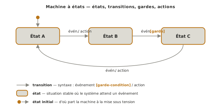
Four ingredients are enough. The generic diagram above puts them on stage. Here they are one by one.
- The states. These are the stable, mutually exclusive situations of the system. Well chosen, they answer the question “what situation am I in while waiting for what comes next?“. A state is not an action under way but a position of waiting for an event. The initial state, the one the machine starts in at power-up, is marked with a filled dot joined to the first state: without it, the behaviour at start-up is undefined.
- The transitions. These are the directed moves from one state to another, triggered by an event (a button pressed, a limit switch reached, a timer elapsed, a reading exceeded). No event, no change of state.
- The guard conditions. A transition can be subject to a boolean condition that allows it or not, written in square brackets
[…]. The event “end of closing” only really closes it[if nothing is in the way]. The guard encodes the safety rules and the special cases directly on the diagram. - The actions (or outputs). What the system does — start a motor, light an LED, send a packet. The action can be attached to the transition (written
/ action) or produced for as long as you are in a state. That distinction has a name (see Special case).
The discipline fits in one sentence: one active state at a time, explicit transitions, and anything not provided for stays in the current state (the system never “falls” into an undefined state).
Example — Automatic gate
A motorised sliding gate driven by one button, two limit switches (top and bottom) and an obstacle sensor. The same system is described below at three levels of quality, from the rough draft to a state machine you can work from.
The diagrams are the French ones, so their labels are in French. The states read Fermé, Ouverture, Ouvert, Fermeture and Bloqué, that is Closed, Opening, Open, Closing and Blocked. The events and actions read bouton, fin haut, fin bas, obstacle, tempo 5 s, / moteur, / stop and / inverser, that is button, top limit, bottom limit, obstacle, 5 s timer, motor, stop and reverse. English names are used in the text below.
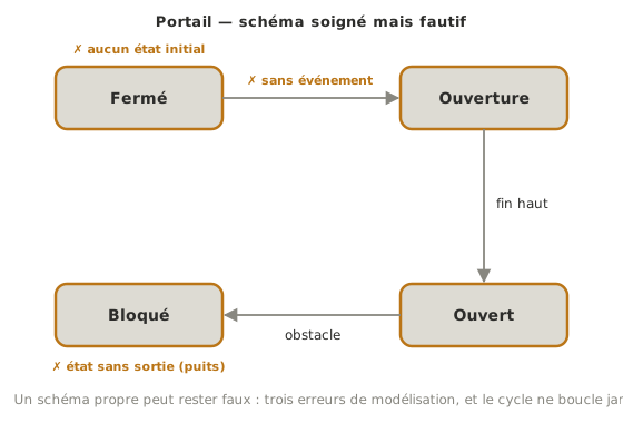
Counter-example — neat drawing, faulty model
Why this is bad. The states are clean, the drawing is neat. And the model has three holes in it. Where do we start from? No initial state: the behaviour at power-up is undefined. What makes it open? The Closed → Opening transition carries no event: it is taken… when? And above all, Blocked is a dead end: no transition leaves it, the cycle never comes round again. As with the flowchart: a neat drawing does not validate the logic.
The real cost. Translated as it stands, the program starts in an unpredictable state and, at the first obstacle, the gate goes into Blocked… for good. The only way out is to cut the power. The bug is not in the code. It was already in the diagram.
Middling version — clean states, hollow transitions
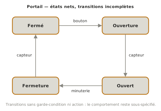
Why this is middling. The four states are clean and exclusive, the cycle is clear. That is already workable. But the transitions stay under-specified: “sensor”, which one? no guard condition, no action noted, and above all nothing that handles the obstacle. A gate that does not know how to react to an obstacle while closing is dangerous. The diagram is readable but incomplete for moving to code.
Target version — a complete state machine
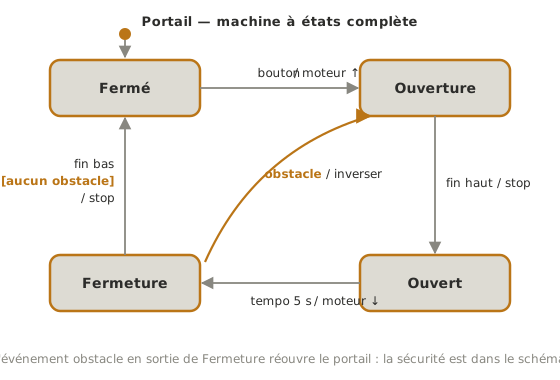
Why this is good. The initial state is marked (the filled dot → Closed: at power-up, the gate takes itself to be closed). Each transition carries what is needed: the event (button, top limit, 5 s timer, obstacle), the guard condition where one is called for (bottom limit
[if nothing is in the way], the gate only declares itself closed if nothing is obstructing it), and the associated action (motor up, stop, reverse). The safety transition, Closing → Opening on the obstacle event, puts safety on the diagram rather than in a patch bolted on afterwards. This diagram transcribes line for line into code (onecaseper state, see the Arduino tutorial).
Pitfalls
States that overlap. If you can “be in two states at once”, they are not states. The test: at any instant, exactly one must be true. Otherwise, merge them or split them differently.
Mixing up state and action. “Opening” is a state (you are waiting for the limit switch). “Open it” is an action. Name the states after situations (Opening, Open), not after verbs of action under way.
Forgetting the initial state. A state machine has to say where it starts from at power-up. An undefined initial state means unpredictable behaviour when the power comes on (compare the state of the GPIOs at boot).
Cases left to chance. For each state, ask what happens if an unexpected event turns up. The sound rule: any event not provided for stays in the current state, it does not cause a silent jump.
Mixing up event and guard. The event triggers the examination of the transition. The guard allows the move. “Limit switch reached” is an event. “If nothing is in the way” is a guard. Muddling them makes the transitions impossible to test.
An explosion in the number of states. Multiplying states to encode every combination of conditions makes the diagram blow up. When that happens, it is often because some piece of data should be a variable (a counter, a mode) rather than a state, or because you should move to a GRAFCET to handle parallelism.
Special case — Moore and Mealy
Two conventions coexist, depending on where the actions are attached. In a Moore machine, the action depends only on the state (for as long as you are in Opening, the motor runs). In a Mealy machine, the action is attached to the transition (on the move Closed → Opening, start the motor). In practice the two get mixed, and the distinction matters mostly for reasoning cleanly: a “continuous” action attaches to a state, a “one-off” action to a transition. The choice has no bearing on the power of the model, only on how readable it is.
See also
- Algorithm — the parent page, which places the state machine among the representations (flowchart, GRAFCET, timing diagram)
- Programming a state machine on Arduino — the C++ implementation with the
switch(state)pattern - Programming a state machine in MicroPython — the same implementation on the Python side
- Flowchart — the alternative for a one-off chain of decisions, with no notion of mode
- GRAFCET — the representation to prefer when sequences advance in parallel
- Proof of concept — where the state machine you designed gets implemented and tested
- Non-blocking programming — the architecture that calls these machines every pass without ever blocking