GRAFCET (GRAphe Fonctionnel de Commande Étapes-Transitions, the French acronym for a step-and-transition control chart) is a standardised graphical language (IEC 60848) that describes the sequential behaviour of an automated system. It represents a control algorithm as steps (what the system does) joined by transitions carrying the conditions for moving on, and it excels wherever several sequences advance in parallel: it is the tool of industrial automation.
What is it for?
For a process that runs through phases (advance, drill, retract, eject), GRAFCET describes the sequence in a way that is unambiguous and shareable. Its strengths:
- it is standardised (IEC 60848) — a GRAFCET chart reads the same way to any automation engineer, it is a common language;
- it cleanly separates what the system does (the actions of the steps) from what makes it move on (the conditions on the transitions);
- it handles parallelism — several simultaneous sequences, something a flowchart or a simple state machine struggle to express;
- it translates directly into programming a PLC (the SFC language is very close to it).
It is the representation to prefer as soon as you are talking about a machine cycle or about automation. For a plain chain of decisions with no parallelism, a flowchart stays lighter.
How to read a GRAFCET chart
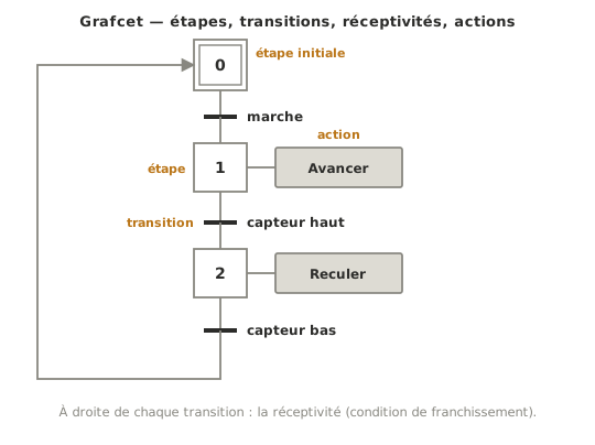
GRAFCET strictly alternates steps and transitions, joined by links read from top to bottom.
- Step (numbered square) — a situation of the system. The initial step (double square) is active at start-up. An active step holds a token. The actions attached to it (boxes to its right) are carried out for as long as the step is active.
- Transition (horizontal bar) — separates two steps and carries a transition condition, called a réceptivité in French: the boolean condition for moving on (a sensor, a button, a logical combination written with
·for AND and+for OR). - Clearing rule: a transition is cleared when the step above it is active AND the condition is true. On clearing, the step above goes inactive and the step below goes active — in the same instant.
A return link (arrowed when it goes back up) closes the cycle. On a plain sequence, only one step is active at a time. Parallelism goes through divergences instead (see Special case).
Example — Drilling station
A station that drills a workpiece then ejects it, in a cycle. At rest (step 0), nothing moves. The chart then runs through four situations.
The diagram is the French one, so its labels are in French: départ, pièce présente, Descendre broche, Remonter, Éjecter and pièce évacuée, that is start, workpiece present, lower the spindle, raise, eject and workpiece cleared.
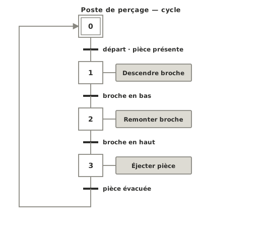
The condition on the first transition, start AND workpiece present, is a logical combination: the cycle only starts if the operator presses start and a workpiece is in place. Each step does one thing and only hands over on the next explicit condition. The sequence is readable, and transcribes as it stands onto a PLC. It is that standardised clarity that makes GRAFCET preferable to a flowchart for a machine cycle.
Pitfalls
Mixing up step and action. The step is a situation (“on the way down”). The action is what you do while in it (“lower the spindle”). The action lives in a box to the right of the step, not inside the square.
A forgotten transition condition. A transition with no condition is cleared straight away. The chart “falls” from one step to the next without waiting for anything. Every transition carries a condition.
A missing initial step. With no double square, the chart does not know which situation to start in. One and only one initial step per chart (parallelism aside).
Several steps active by mistake. On a plain sequence, only one step should be active at a time. Several tokens at once, where none were intended, give away a badly placed divergence or a badly closed loop.
Mixing up the chart and the PLC code. GRAFCET describes the requirements for the behaviour (IEC 60848). It is very close to a PLC’s SFC language, but it stays a specification, not the program itself.
An AND divergence never closed. What opens in parallel (AND divergence) has to be resynchronised (AND convergence). Forgetting the convergence leaves branches that never meet again.
Special case — AND and OR divergences
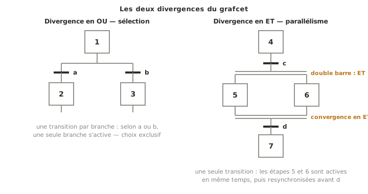
Two structures set GRAFCET apart from purely sequential representations. The OR divergence (sequence selection): several transitions leave the same step, and depending on the conditions only one branch is taken, an exclusive choice. The AND divergence (parallelism): a single transition activates several steps at once, launching parallel sequences, which will have to be resynchronised by an AND convergence. It is that ability to handle parallelism that makes GRAFCET what it is. A flowchart or a simple state machine do not express it naturally.
See also
- Algorithm — the parent page, which places GRAFCET among the representations
- State machine — close in spirit, but with no standardised parallelism and no PLC framing
- Flowchart — lighter for a chain of decisions with no cycle and no parallelism
- Timing diagram — complementary, for checking the timing of a cycle’s signals
- Proof of concept — where the sequence gets implemented and tested