An algorithm is a finite sequence of unambiguous operations that turns inputs into outputs in order to solve a problem, here driving the behaviour of an embedded system. Before writing it as code, you represent it: a diagram makes the logic visible, shareable across the team and open to criticism before a single line is typed. This page is the way in to the four representations most often used on a project — the flowchart, the state machine, the GRAFCET and the timing diagram — and it gives you the method for choosing the right one for what you are trying to describe.
What is it for?
Coding a slightly rich behaviour straight away (a cycle, several modes, nested conditions) soon leads to a tangle of if statements that nobody reads back. Representing the algorithm before programming serves to:
- clarify the logic — lay out the cases, the conditions and the order of operations flat, outside any language;
- communicate — a diagram can be discussed in a team review, where code can only be endured;
- catch the gaps early — a forgotten case (what happens if the sensor does not answer?) leaps out of a diagram, not out of 200 lines;
- prepare the code — a good representation turns almost mechanically into program structure.
This representation is built during the concept phase (when the expected behaviour is defined) and checked during the proof of concept (when it is implemented and tested).
How to choose a representation
The four representations do not describe the same thing. The choice depends on the nature of the behaviour: a chain of decisions, a succession of states, parallel steps, or timing relationships between signals.
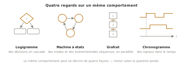
| Representation | Describes well | Form | When to use it |
|---|---|---|---|
| Flowchart | a chain of decisions and actions | diamonds (tests) and rectangles (actions) joined by arrows | a linear treatment with branches (if… then… else) |
| State machine | a system that stays in one state until an event occurs | states joined by conditional transitions | a sequential behaviour with modes (idle / running / alarm, opening / closing…) |
| GRAFCET | a sequential process, possibly with parallel steps | standardised steps and transitions (IEC 60848) | industrial automation, sequences with simultaneous actions |
| Timing diagram | how several signals evolve over time | logic levels or curves on a shared time axis | checking timing relationships (what changes before what, durations, edges) |
To settle it. If the behaviour is a one-off cascade of decisions, a flowchart is enough. If the system changes mode and reacts differently depending on where it stands, it is a state machine, the most frequent case on a mechatronics project. If several sequences advance in parallel (typical of an automation system), GRAFCET is built for it. And for reasoning about timing (does one signal have to rise before the other, how long a pulse lasts), none of the other three replaces the timing diagram.
These representations do not rule each other out: the overall architecture is often described as a state machine, then the detail of one treatment as a flowchart, and a timing constraint checked on a timing diagram.
What about pseudocode? An algorithm can also be written out in text — short sentences, imperative, outside any language (see the L298N example in reading a datasheet). It is the fastest representation to write, ideal for a rough draft or for specifying a single function. Diagrams take over as soon as the modes and the branches multiply.
The storytelling test
An algorithm you cannot tell in plain words is not ready to be coded: saying it out loud is the first detector of woolly ideas. But the reverse does not hold. Plain language tolerates ambiguities that code refuses (“the gate opens when somebody arrives”… and what if somebody arrives while it is closing?). It is going through a representation that flushes them out. The healthy chain: tell it, represent it, code it.
See also
- State machine — the representation of choice for sequential behaviour with modes
- Flowchart — the chain of decisions and actions
- GRAFCET — the standardised sequence, with parallelism, of automation
- Timing diagram — timing relationships between signals
- Microcontroller — the target that will run the algorithm once it is coded