PWM (Pulse Width Modulation) puts out a fast square wave whose proportion of time spent at HIGH you can vary, the duty cycle. On Arduino, the analogWrite() function generates that signal on the pins marked with a tilde ~. From the point of view of a load (LED, motor, heating element) that is slow compared with the PWM frequency, the effect is equivalent to an average voltage adjustable from 0 to 5 V, without the pin ever producing any real intermediate voltage.
What is it for?
PWM is the universal tool for varying the power delivered to a load without burning energy in a variable component (a potentiometer, a transistor in its linear region). Three typical uses on a school project:
- Varying the brightness of an LED — fading, animation, progressive indicator.
- Setting the speed of a DC motor — paired with an H-bridge (see driving a DC motor).
- Driving a servo — the position is encoded by the width of a pulse (a special case handled by the
Servo.hlibrary, see servo).
It is also the basis of regulated heating (heating element plus thermocouple) and of the DC dimmer.
Step by step
Four steps: find a PWM pin, wire it, write the code, watch it.
1. Find a PWM pin
Not every digital pin generates PWM. On the Arduino Uno R3, six pins support it: D3, D5, D6, D9, D10, D11 (marked with a ~ next to the number on the silkscreen).
- On the Mega 2560: 15 PWM pins (D2-D13, D44-D46).
- On the Nano: D3, D5, D6, D9, D10, D11.
- On the Uno R4: D3, D5, D6, D9, D10, D11 (compatibility preserved, but different resolution and frequency).
For any other microcontroller (ESP32, STM32, RP2040…), the PWM pins cannot be guessed: go to the manufacturer’s pinout diagram or to the board’s technical documentation, which show the pins capable of PWM (often marked PWM, TIM or ~).
analogWrite() on a non-PWM pin raises no error: it simply forces HIGH (if the value is above 127) or LOW. Symptom: the LED stays lit at full power or dark, whatever value you pass.
2. Wire a PWM LED
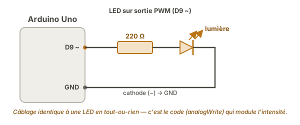
LED anode (+) → 220 Ω resistor → pin D9 (PWM); cathode (−) → GND. Same wiring as an LED on an on/off output. It is the code that changes.
3. Write the code — progressive fade
const int LED = 9;

void setup() {
  pinMode(LED, OUTPUT);
}

void loop() {
  // Fade up: 0 → 255
  for (int v = 0; v <= 255; v++) {
    analogWrite(LED, v);  // applies the duty cycle v/255
    delay(8);             // 8 ms per step → a fade of about 2 s
  }
  // Fade down: 255 → 0
  for (int v = 255; v >= 0; v--) {
    analogWrite(LED, v);  // same principle, decreasing value
    delay(8);
  }
}
The parameter of analogWrite() is an integer from 0 (0% duty cycle, output always low) to 255 (100% duty cycle, output always high). That 0-255 range stays the default on the Uno R4 too. A higher resolution is only available as an option through analogWriteResolution(). The LED lights up progressively then dims progressively, over and over.
4. Watch it
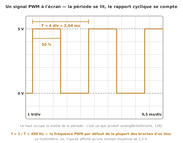
To the naked eye, the LED varies in brightness: that is the effect of perceptual averaging (the eye integrates the ~490 switchings per second of Arduino PWM on D9). On an oscilloscope, you see the true nature of the signal: a 0-5 V square wave whose proportion of time at 5 V varies with the value passed (idealised timing diagrams in PWM).
Example — LED dimmer with a potentiometer
The full case: read the position of a potentiometer on A0 and use it as the setpoint for the brightness of the LED.
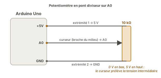
Wiring: a 10 kΩ potentiometer on A0 (wiper), 5 V and GND on the ends; LED plus 220 Ω on D9.
const int POT = A0;
const int LED = 9;

void setup() {
  pinMode(LED, OUTPUT);
}

void loop() {
  int valeur = analogRead(POT);       // 0-1023
  int pwm    = valeur / 4;            // 0-255 (scaling)
  analogWrite(LED, pwm);
  delay(10);
}
Turn the potentiometer: the brightness of the LED follows. Note: analogRead() returns 0-1023 on the Uno R3 (see reading an analog sensor), but analogWrite() wants 0-255. The conversion by dividing by 4 (or the map() function) is compulsory.
Pitfalls
Not a PWM pin. The code compiles, analogWrite() raises no error, but the output is binary. Check the ~ on the board’s silkscreen or in the documentation.
Confusing analogWrite() with a real analog output. analogWrite() does not put out an analog voltage: it puts out a 0/5 V square wave with a variable duty cycle. The average voltage is analog for a slow load (LED, motor), but the instantaneous value stays binary. For a real analog voltage you need a DAC (the Uno R4 has one on A0) or an RC low-pass filter on the PWM output.
Confusing 0-255 with 0-100. The parameter of analogWrite() is 0-255 (8 bits), not 0-100 or 0-1023. A value of 100 means a 39% duty cycle, not 100%.
Default PWM frequency unsuited to the job. On the Uno, pins D5 and D6 run at ~980 Hz, the others at ~490 Hz. For an LED or a slow motor that is imperceptible. For a fast motor with little inertia, or for a piezo buzzer, the frequency can be audible or produce artefacts. See hardware timers to reconfigure the frequency.
Inductive load (motor, coil) with no flyback diode. A coil driven by PWM produces overvoltages at every switching. With no 1N4007 diode reversed across it, the switching transistor (or the pin itself, though that is already past its current rating) dies quickly.
PWM on a big load with no transistor. The duty cycle does not change the current: full power is full power. A 1 A motor driven by PWM still draws 1 A during the high phases. The Arduino pin (20 mA maximum) cannot take it. Always a transistor (a MOSFET for the higher currents) or an H-bridge.
Clash with libraries (Servo.h, Tone.h). Some libraries use the same timers as analogWrite(). Including Servo.h disables PWM on D9 and D10 on the Uno. Read the notes of the library you are using.
Special case — Smoothing with an RC filter for a real voltage
To turn PWM into a real smoothed DC voltage (to drive the analog input of another instrument, for instance), an RC low-pass filter on the output is enough. Typical values: R = 10 kΩ, C = 1 µF, cut-off frequency ~16 Hz (well below the 490 Hz of Arduino PWM, so the smoothing is effective). The trade-off: a response time of a few tens of milliseconds.
For high-precision applications (audio DAC, fast modulation), prefer a proper external DAC (an MCP4725 over I2C, for example).
Where it fits in the project
- Step 2 of the proof of concept phase — every load with variable power (an indicator LED with adjustable brightness, a cooling fan, a DC motor) is first validated with PWM on an isolated bench.
- Step 3 of the proof of concept phase — when a measurement is processed by a control loop, the command downstream often goes through PWM (see PID control).
- Step 3 of the integration and testing phase — driving the actuators integrated into the whole system.
PWM is the power-modulation tool par excellence on a school project — cheap in silicon, well supported on the software side, enough for 95% of what you need in motor speed and brightness.
See also
- Arduino — hub of the Arduino tutorials
- off output — prerequisite (digitalWrite, switching transistors)
- Driving a DC motor — the flagship application of PWM, through an H-bridge
- Driving a servo — another kind of PWM, wrapped up by
Servo.h - Hardware timers — to change the PWM frequency
- PWM — the cross-cutting concept page