Using a hardware timer on Arduino means setting up an internal counter so that an action runs at a precise interval (usually through a library such as TimerOne, which hides the registers). The timer fires an interrupt at the frequency you choose, which gives a perfectly steady rate that a millis() loop cannot guarantee, and it also lets you set the frequency of a PWM signal.
What is it for?
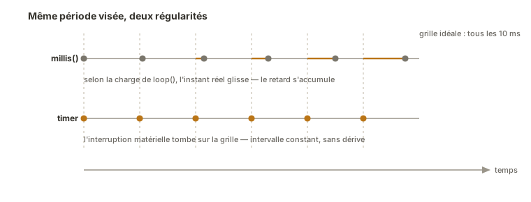
To pace a task, the beginner’s reflex is millis() inside loop(). That is enough for a blink, but the rate drifts as soon as the loop does work of varying length: from one pass to the next, the real interval is never quite the same. For sampling, filtering or PID control, that wobble corrupts the maths. A hardware timer settles the question:
- it fires the action on an interrupt, at exactly the programmed frequency, whatever the loop happens to be doing;
- it frees
loop()from its role as a stopwatch; - it also serves to change the frequency of a PWM (motor speed, LED flicker).
You put one in place during the proof of concept, as soon as a function needs a time base it can trust. For loose, non-critical timing, [[arduino-temporisation-en|millis()]] stays simpler: the hardware timer is for what has to be precise and regular.
Step by step
Four steps: pick a free timer, set it up through the library, attach the periodic function to it, then keep that function minimal.
1. Pick a free timer
An Uno has three timers — Timer0, Timer1, Timer2 — but they are not all available: Timer0 runs millis() and delay(), and several are taken by analogWrite() depending on the pins. Timer1 (16-bit) is the one most often free and the handiest, as long as you are not using the Servo library, which claims it for itself. Touching Timer0 upsets millis(), so leave it alone (see the timer concept page, a shared resource).
2. Set the timer up through the library
The TimerOne library (install it from the library manager) sets the period in microseconds in a single line. For 100 Hz, the period is 10000 µs.
#include <TimerOne.h>

void setup() {
  Timer1.initialize(10000);   // period in microseconds: 10000 us = 100 Hz
}
The library works out the matching prescaler and compare value for us: exactly the job described in the timer concept page, done automatically.
TimerOne only works on AVR boards (Uno R3, Nano, Mega). On an Uno R4 (Renesas) or an ESP32, the timer architecture differs and you go through other libraries (FspTimer on the R4, the native timerBegin() timers on ESP32). The principle, a hardware counter firing a periodic interrupt, stays the same.
3. Attach the periodic function
Timer1.attachInterrupt() ties a function to the timer: it will be called as an interrupt service routine, once per period.
void onTimer() {        // runs every 10 ms, in an interrupt
  // ... regular action ...
}

void setup() {
  Timer1.initialize(10000);
  Timer1.attachInterrupt(onTimer);
}
That function is an ISR: it obeys the rules of interrupts — short, no delay() and no Serial, and any variable shared with loop() declared volatile.
4. Keep the ISR minimal, do the work in loop()
The ISR does the bare minimum, often just raising a flag, and loop() does the heavy work (read, compute, display) when it sees the flag go up. That way Serial, which is off limits inside the ISR, happens where it belongs.

Example — Sampling a sensor at 100 Hz
You read an analog input exactly one hundred times per second, to feed a filter or a constant-step control loop. The timer sets the pace, the ISR raises a flag, the loop reads and sends the measurement.
#include <TimerOne.h>

const int CAPTEUR = A0;
volatile bool echeance = false;      // flag shared ISR <-> loop: volatile

void onTimer() {                     // ISR: every 10 ms, just raise the flag
  echeance = true;
}

void setup() {
  Serial.begin(115200);
  Timer1.initialize(10000);          // 10000 us = 100 Hz
  Timer1.attachInterrupt(onTimer);
}

void loop() {
  if (echeance) {                    // fires at a steady rate
    echeance = false;
    int mesure = analogRead(CAPTEUR);
    Serial.println(mesure);          // Serial here, inside loop(), not in the ISR
  }
}
Sampling falls every 10 ms whatever the load on the loop, because it is the hardware holding the clock. The ISR does no more than signal that the moment has come. All the logic stays in loop(). Next to a rate driven by millis(), the regularity comes with no drift at all, and that changes everything for signal processing.
Special case — Under the hood: the registers
What TimerOne does can be written straight onto the AVR registers, in CTC mode (Clear Timer on Compare). It takes more lines and it is specific to the chip (the Uno’s ATmega328P), but it shows the real machinery described in the concept page: a prescaler, a compare value, an interrupt on compare. The bitwise operations it uses — masking, setting with |=, shifting with << — are spelled out in bit manipulation. The TIMER1_COMPA_vect ISR raises the same volatile echeance flag as the example above.
void setup() {
  cli();                       // interrupts off while we configure
  TCCR1A = 0;
  TCCR1B = 0;
  TCNT1  = 0;
  OCR1A  = 2499;               // f = 16 MHz / (prescaler 64 x (2499 + 1)) = 100 Hz
  TCCR1B |= (1 << WGM12);      // CTC mode
  TCCR1B |= (1 << CS11) | (1 << CS10);   // prescaler 64
  TIMSK1 |= (1 << OCIE1A);     // interrupt on compare match A
  sei();                       // interrupts back on
}

ISR(TIMER1_COMPA_vect) {       // the routine, fired on every compare match
  echeance = true;
}
How to read this code
The block reads in five moves.
cli()turns interrupts off while we configure (otherwise one of them could land on a half-set timer). We clear the control registers (TCCR1A/TCCR1B) and the counter (TCNT1).OCR1Ais the compare value: the counter climbs up to it, then the interrupt goes off. That is what fixes the period.WGM12selects CTC mode (the counter clears itself on every compare match).CS11 | CS10set the prescaler to 64.OCIE1Aenables the interrupt on compare match A. Finallysei()turns interrupts back on. From then on,ISR(TIMER1_COMPA_vect)runs by itself on every compare match.
The formula f = 16 MHz / (prescaler x (OCR1A + 1)) is the concrete form of the frequency ÷ (prescaler × value) from the concept page. On a project the library is almost always enough. This level of detail only earns its keep for fine tuning, or for making sense of existing code.
Special case — Changing the frequency of a PWM
analogWrite() produces a PWM at a fixed default frequency (around 490 Hz on most Uno pins). When that frequency causes trouble — a motor whistling in the audible range, an LED flickering on camera — you change it by reconfiguring the prescaler of the timer driving the pin. Watch out: this setting affects every PWM pin carried by that same timer, and touching Timer0 upsets millis(). It is an advanced use, to be handled with the timer map in mind.
Pitfalls
Reconfiguring Timer0. It runs millis() and delay(): hijacking it breaks every piece of software timing in the program. Barring a very specific need, leave it be.
Forgetting volatile. A variable shared between the timer ISR and loop() without volatile can be read stale: the flag never seems to go up. A rule shared by all interrupts.
Doing too much in the timer ISR. Serial, heavy computation, delay(): none of them belong in the ISR. It signals, the loop handles. An ISR that overruns its period gets caught by the next one and the system falls apart.
A period too short for the work asked of it. Running an ISR at 10 kHz when it takes more than 100 µs to execute leaves no time at all for loop(). Check that the period matches what you are asking it to do.
Two libraries fighting over the same timer. TimerOne and Servo both want Timer1: using them together produces erratic behaviour. One timer, one owner.
Believing a millis() rate is worth a timer rate. For anything precise it is not: only the hardware base guarantees regularity. That is the criterion for choosing between [[arduino-temporisation-en|millis()]] and a timer.
Where it fits in the project
- Step 2 of the proof-of-concept phase — sampling or pacing a function at constant step on an isolated bench, a prerequisite for any clean measurement or control loop.
- Step 3 of the integration and testing phase — the system’s command loop (a PID control loop, for instance) runs at a fixed period imposed by a timer, which is the condition of its stability.
Having a hardware time base you can trust is what separates a rig that “roughly works” from a system whose behaviour in time is under control, and it becomes indispensable the moment you close a loop.
See also
- Timer — the parent concept: counter, prescaler, overflow, compare match (worth understanding before writing code)
- Arduino — hub for the Arduino tutorials
- Interrupt — the mechanism through which the timer runs its periodic routine
- delay() vs millis() — software timing, the imprecise alternative
- Driving a PWM output —
analogWrite(), whose frequency this tutorial lets you set - PID control — a direct use of constant-step sampling
- ESP32 — native timers (
timerBegin), in place of TimerOne which is AVR-only