Setting up an external interrupt on Arduino means tying a function, the interrupt service routine (ISR), to a pin through attachInterrupt(), so that it runs automatically on every edge of the signal without the loop() having to watch the pin. It is the tool for counting fast pulses or reacting instantly to an event, even while the loop is busy elsewhere.
What is it for?
Reading a pin with digitalRead() inside loop() is not enough when the signal is too brief or the loop too busy: the pulse slips between two passes and is never seen. Putting the pin on an interrupt settles the question:
- the pulse is caught by the hardware, at the exact instant it arrives (you never miss one);
- the reaction is immediate, whatever the loop is doing at that moment;
- the loop stays free to display, compute or communicate between two pulses.
It is the reflex as soon as you have to count the ticks of a speed sensor, the passes of a flow meter, the steps of an encoder, or react without delay to a critical button. You put it in place during the proof of concept, when the time comes to capture a sensor signal.
Step by step
Four steps: find a pin that can interrupt, write a short ISR, attach it, then read its result cleanly in loop().
1. Find a pin that can interrupt
Not every pin can fire an external interrupt. On an Uno / Nano, only D2 and D3 can. A Mega offers six, a Leonardo five, an ESP32 nearly all of them. The digitalPinToInterrupt(pin) function turns a pin number into an interrupt number: always use it rather than writing the interrupt number by hand, so the code stays portable.
| Board | External interrupt pins |
|---|---|
| Uno, Nano, Mini (ATmega328) | D2, D3 |
| Mega, Mega2560 | D2, D3, D18, D19, D20, D21 |
| Leonardo, Micro | D0, D1, D2, D3, D7 |
| ESP32 | nearly all GPIOs |
Two pitfalls can be read off this table. On a Mega, D20 and D21 are also the I2C pins: they stop being available for interrupts the moment an I2C bus is running. And on a Leonardo, D0 and D1 are the serial port. In practice that leaves D2, D3 and D7.
2. Write the ISR
The ISR is a void function, with no argument and no return value. It has to stay minimal: here, incrementing a counter. The variable shared with loop() is declared volatile, otherwise the main program might never see it updated.
volatile unsigned long impulsions = 0;   // shared ISR <-> loop: volatile

void compter() {                          // the ISR: short, no delay and no Serial
  impulsions++;
}
No delay() and no Serial.print() inside the ISR: those functions rely on interrupts, which are disabled while it runs. You count, and that is all. Displaying happens in loop().
3. Attach the interrupt
Inside setup(), attachInterrupt() ties together the pin, the ISR and the trigger mode.
const byte BROCHE_CAPTEUR = 2;            // D2 on an Uno

void setup() {
  pinMode(BROCHE_CAPTEUR, INPUT_PULLUP);
  attachInterrupt(digitalPinToInterrupt(BROCHE_CAPTEUR), compter, FALLING);
  Serial.begin(9600);
}
The mode says what fires the ISR: RISING (rising edge), FALLING (falling edge), CHANGE (both), LOW (for as long as the pin is low). To count pulses you pick a single edge (FALLING here) so that each pulse is counted once and not twice. detachInterrupt(digitalPinToInterrupt(BROCHE_CAPTEUR)) would let you switch it off.
4. Read the counter cleanly in loop()
The loop reads the counter without blocking anything, at a rate given by millis() (no delay()). One precaution is needed: impulsions is four bytes long, and on an Uno (8-bit) the processor reads it in several successive accesses. If a pulse arrives between those accesses, the ISR changes the variable in the middle of the read and loop() gets back an inconsistent value (half old, half new).
So the read is protected by a critical section: noInterrupts() briefly disables every interrupt, you copy the value into n (and reset impulsions to 0), then interrupts() re-enables them. For those two or three instructions, no ISR can run: the copy is atomic, all or nothing, never half done. That parenthesis has to stay as short as possible. Leave interrupts off too long and you would end up missing a pulse, which is the very thing you were trying to avoid.
unsigned long tAffichage = 0;

void loop() {
  if (millis() - tAffichage >= 1000) {    // once per second
    tAffichage = millis();

    noInterrupts();                        // critical section: atomic read
    unsigned long n = impulsions;
    impulsions = 0;
    interrupts();

    Serial.print(n);
    Serial.println(" pulses/s");
  }
}
Example — A Hall effect speed counter
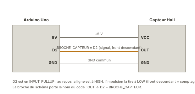
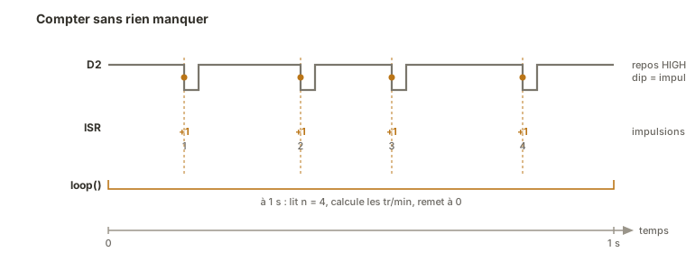
A Hall effect sensor detects a magnet fixed to a wheel going past: one brief pulse per turn. At high speed those pulses are too close together and too short to be read reliably inside loop(). It is the textbook case for an interrupt. You count the pulses on an interrupt, and the loop works out the rotation speed once a second.
const byte BROCHE_CAPTEUR = 2;            // Hall sensor output on D2
const byte IMPULS_PAR_TOUR = 1;          // 1 magnet => 1 pulse per turn

volatile unsigned long impulsions = 0;
unsigned long tAffichage = 0;

void compter() {                          // ISR: one more pulse
  impulsions++;
}

void setup() {
  pinMode(BROCHE_CAPTEUR, INPUT_PULLUP);
  attachInterrupt(digitalPinToInterrupt(BROCHE_CAPTEUR), compter, FALLING);
  Serial.begin(9600);
}

void loop() {
  if (millis() - tAffichage >= 1000) {
    tAffichage = millis();

    noInterrupts();                        // atomic copy of the counter
    unsigned long n = impulsions;
    impulsions = 0;
    interrupts();

    float toursParSec = (float)n / IMPULS_PAR_TOUR;
    Serial.print(toursParSec * 60.0);     // converted to rpm
    Serial.println(" rpm");
  }
}
How to read this code
Once a second,
loop()collects the counter. The copyn = impulsionsand the resetimpulsions = 0are wrapped inside thenoInterrupts()/interrupts()critical section (see step 4): you read and reset without a pulse slipping in between the two. Counting over one second then starting again from zero turns a total into a frequency (pulses per second). The last line converts that into revolutions per minute (× 60).
The ISR does nothing but increment. All the computing (conversion to rpm, display) happens in loop(), where Serial.print() is allowed and where the computing time bothers nobody. The loop stays responsive, and no pulse is lost even at full speed. Wiring a second sensor to D3 would come down to adding a second ISR: the two counts live side by side without getting in each other’s way.
Pitfalls
Forgetting volatile. A variable shared with the ISR without volatile can be read stale: the counter looks frozen even though the ISR is incrementing it properly. Any variable touched by the ISR and read in loop() is volatile.
Reading the counter without a critical section. On an Uno (8-bit), reading an unsigned long (4 bytes) takes several accesses. If the interrupt lands in the middle, you read an inconsistent value. The copy goes between noInterrupts() and interrupts().
Putting delay() or Serial in the ISR. Those functions depend on interrupts, which are disabled while the ISR runs: they either hang there or return nonsense. The ISR does the bare minimum and no more.
Picking a pin with no interrupt. On an Uno, attaching an interrupt to anything other than D2 or D3 fires nothing at all, silently. Check the board’s pins before you wire.
Counting a mechanical button with no debouncing. A button bounces: a single press can generate several edges, so several triggers. An interrupt does not filter bounce. To count presses you need debouncing on top, in software or in hardware.
Doing too much work on every pulse. If the ISR has to do more than increment or store, that usually means the processing belongs to loop(). The ISR signals, the loop handles.
Special case — Interrupts on ESP32
On ESP32, nearly every pin accepts an interrupt, and attachInterrupt() is used in the same way. One extra requirement comes with it: the ISR has to sit in fast internal memory, with the IRAM_ATTR attribute in front of its declaration (void IRAM_ATTR compter() { … }), failing which the program may crash. Sharing variables with volatile and reading atomically still apply. The detail belongs to the ESP32 module.
Where it fits in the project
- Step 2 of the proof-of-concept phase — capturing a fast sensor signal (speed, flow, position) on an isolated bench, to validate the acquisition chain before integrating it.
- Step 3 of the integration and testing phase — interrupt-based measurement, once validated on its own, feeds the closed-loop control of the complete system (a turn count feeding a speed control loop).
Running in the attachInterrupt plus atomic-read pairing on a simple counter gives you the reusable reflex for any signal too fast to poll — encoders, flow meters, tachometers on the project.
See also
- Interrupt — the parent concept: mechanism, ISR,
volatile, atomicity (worth understanding before writing code) - Arduino — hub for the Arduino tutorials
- delay() vs millis() — the non-blocking timing used to pace the display
- off input — debouncing, indispensable for counting button presses
- Timers on Arduino — the other big source of interrupts: pacing a task at a regular interval
- ESP32 — interrupts there require the
IRAM_ATTRattribute on the ISR