The GPIO (general purpose input/output) pins of the Pico are the digital pins that can be configured as an input or an output, to read or emit a binary signal (0 V / 3.3 V). In MicroPython, everything goes through the Pin class of the [[micropython-modules-en|machine]] module. Configuring a GPIO correctly is the basic move of any embedded program. Forgetting the mode, mixing up the pulls or ignoring the floating state of an input is the most frequent cause of unpredictable behaviour early in a project.
What is it for?
Every binary sensor and actuator (button, limit switch, LED, relay, buzzer, presence sensor) goes through the GPIO. Three configurations cover the essentials: output (Pin.OUT, driven to 1 or 0), input pulled high (Pin.IN, Pin.PULL_UP), input pulled low (Pin.IN, Pin.PULL_DOWN). Understanding these modes and the wiring that goes with them makes most of the other tutorials readable.
Step by step
Four steps: identify the pin, create the Pin object with its mode, read or write, wire it cleanly.
1. Identify the pins
The Pico exposes pins GP0 to GP28 (the GP numbering, not to be confused with the physical pin numbering). Specifics: GP26 / GP27 / GP28 double as analog inputs (ADC). Some pins carry a bus by default (UART, I2C, SPI). The on-board LED is on GP25 (shorthand "LED").
Every pin runs at 3.3 V and is not 5 V tolerant — see logic levels.
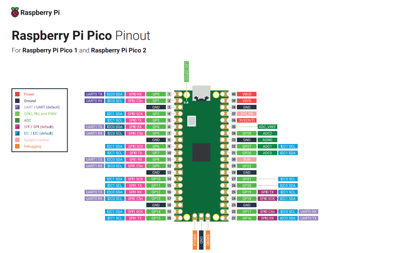
Source: Raspberry Pi Ltd — CC BY-ND licence, image unmodified.
2. Create the Pin object with its mode
Unlike Arduino (pinMode inside setup()), you create one object per pin, usually at the top of the program:
from machine import Pin

led = Pin(15, Pin.OUT)                 # output
bouton = Pin(14, Pin.IN, Pin.PULL_UP) # input, internal resistor to 3.3 VPin.OUT— the pin drives a signal outwards (LED, relay, transistor).Pin.IN, Pin.PULL_UP— input with an internal resistor to3.3 V. Inverted logic: reads1at rest,0when connected to GND (typically through a button).Pin.IN, Pin.PULL_DOWN— input with an internal resistor to GND: reads0at rest,1when brought to 3.3 V. (The Pico offers both pulls internally — an advantage over the Arduino’s AVR, which only has a pull-up.)Pin.INon its own — a floating input, with no bias: the reading is random if nothing is connected. Keep it for cases with an external resistor.
3. Read or write
while True:
    if bouton.value() == 0:    # button pressed (pull-up: 0 = pressed)
        led.on()
    else:
        led.off()
bouton.value() returns 1 or 0. On the output side, led.value(1)/led.value(0), or the shorthands led.on() / led.off() / led.toggle().
4. Wire it cleanly
- Output to a LED: a series resistor of 220 Ω to 1 kΩ between the pin and the anode (+) of the LED, cathode (−) to GND. Without a resistor, the LED or the pin gets damaged.
- Input from a button,
PULL_UP: one side of the button to the pin, the other side to GND. Nothing else. - Input from a button,
Pin.INalone: an external resistor is needed (~10 kΩ to 3.3 V or to GND) to give a defined rest state.
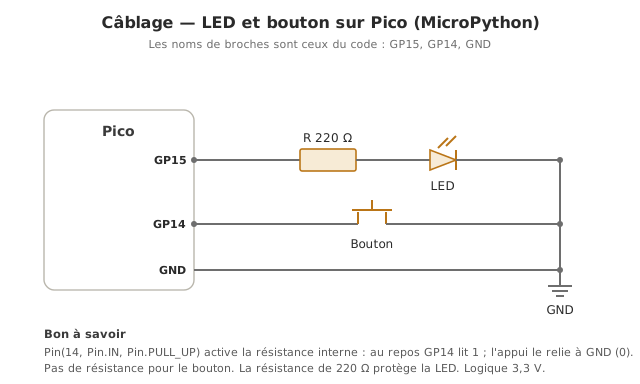
Example — A button that lights a LED
Complete wiring and code to validate Pin.OUT plus Pin.IN plus read and write.
Wiring: LED anode → 220 Ω resistor → GP15; cathode → GND. Button between GP14 and GND (PULL_UP, no external resistor).
from machine import Pin

led = Pin(15, Pin.OUT)
bouton = Pin(14, Pin.IN, Pin.PULL_UP)

while True:
    if bouton.value() == 0:
        led.on()
    else:
        led.off()
Run it, press the button, and the LED comes on. Release it, and the LED goes out. If the LED stays on permanently, you have probably wired one side of the button to 3.3 V instead of GND.
Pitfalls
A floating pin. An input left in Pin.IN with no pull picks up noise — a random reading that can look as if it responds to a hand passing nearby (a 50 Hz antenna effect). For a button, it is almost always PULL_UP plus a button to GND.
The inverted logic of the pull-up. A button on PULL_UP reads 0 when pressed. Testing if bouton.value() == 1 will light the LED when the button is released — the opposite of what you expect.
A LED with no resistor. A LED connected directly draws an excessive current that burns it out (or damages the pin). Always a series resistor (220 Ω to 1 kΩ for a standard LED on 3.3 V).
Maximum pin current exceeded. A Pico pin delivers about 4 mA by default, about 12 mA at most (the drive strength is adjustable). That is less than an Arduino (20 mA), so you reach for a transistor or a dedicated module even sooner (see off output).
The 5 V reflex. The Pico is not 5 V tolerant: applying 5 V to an input can destroy the pin. Shift the level of a 5 V sensor (voltage divider or level shifter).
Special case — PWM, ADC and buses
Not all pins are equivalent:
- ADC — GP26 / GP27 / GP28 are the analog inputs ([[micropython-capteur-analogique-en|
ADC]]). - PWM — on the Pico, every GPIO pin can generate a PWM signal (see PWM) — no dedicated “
~” pins as on Arduino. - Buses — some pins carry UART, I2C or SPI by default (see communication buses). Using a pin as GPIO makes it unavailable for its bus.
The board’s official pinout is the reference. Keep it within reach.
Where it fits in the project
- Step 2 of the proof of concept phase — first individual input and output trials (button, LED, limit switch) before assembling anything.
- Step 2 of the integration and testing phase — piece-by-piece validation of the I/O before the test pyramid.
Mastering these modes on a small isolated setup is the foundation that almost every following tutorial rests on — no point moving on to sensors or actuators before that groundwork is firm.
See also
- MicroPython — the module hub
- GPIO — cross-cutting concept page (modes, state at boot, GPIO on other families)
- off input — the natural next step (a button with debouncing)
- off output — output beyond the LED (relays)
- Configuring Arduino GPIO — the C++ equivalent, worth comparing
- Logic levels — 3.3 V, the Pico is not 5 V tolerant