Between the instant the Pico is powered and the instant main.py runs its first useful instruction, there is a short delay (firmware plus script launch) during which the state of the GPIO is not the one you coded: they sit as high-impedance inputs (floating). What that means in practice: a relay can pull in briefly, a motor can jerk, an LED can flash at start-up. The good news: the Pico is simpler than the ESP on this point. It has no strapping pins that change the boot mode according to their level.
What is it for?
Three cases where you need to understand the GPIO state at boot: an actuator that comes on at start-up (a relay that clicks, a motor that twitches), pins reserved by the board (not to be used), a safe state after a power cut or a restart (coming back to a state that is not dangerous).
Step by step
Four steps: understand the sequence, spot the reserved pins, add an external pull resistor, initialise cleanly from the first lines of code.
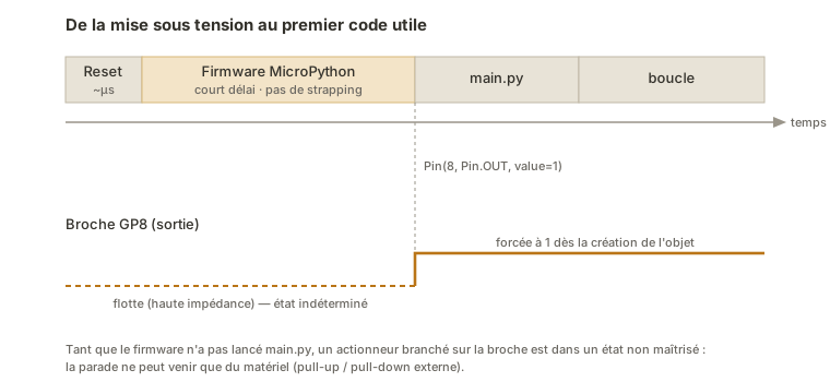
1. Understand the start-up sequence
- Power-up or reset — every pin a floating input (high impedance).
- MicroPython firmware start-up (a short delay).
main.pylaunch — the pins are configured as thePinobjects are created.- Loop — normal behaviour.
During phases 1 and 2, any pin later used as an output floats: an actuator wired to it is in an undefined state. Unlike the ESP8266 or the ESP32, no pin of the Pico has to sit at a given level for it to boot — no blocking boot trap.
2. Spot the pins reserved by the board
The Pico reserves a few pins for its own operation — not to be used for general purposes:
| Pin | Internal role |
|---|---|
| GP23 | power mode control (SMPS) |
| GP24 | VBUS sensing (USB present) |
| GP25 | built-in LED |
| GP29 | VSYS measurement (ADC3) |
(On the Pico W and Pico 2 W, some of these functions go through the wireless chip — the LED in particular, hence the Pin("LED") shortcut.) The BOOTSEL button is not a user pin: holding it down at power-up deliberately puts the board into mass storage mode, for reflashing.
3. Add an external pull resistor where you need one
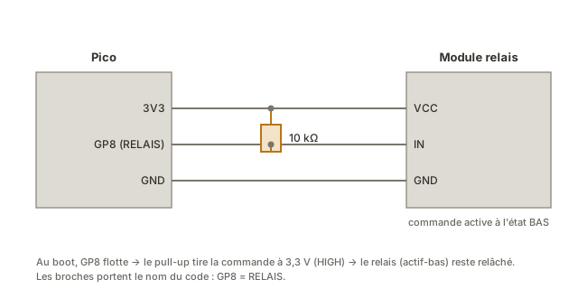
A pin left floating at boot is settled by an external resistor: pull-down (10 kΩ to GND) so that the actuator stays off until the code has taken control; pull-up (10 kΩ to 3.3 V) for an actuator that is active at rest (a module with an active-low input). For an active-low relay module, an external pull-up keeps the relay released during the boot — the generic answer to the “relay click at start-up”.
4. Initialise cleanly as the object is created
MicroPython offers a neat answer the Arduino does not have: the Pin constructor accepts an initial value (value=), applied as soon as the pin is configured as an output — with no transit through 0:
from machine import Pin

# The (active-low) relay starts straight in the released state (1), never passing through 0
relais = Pin(8, Pin.OUT, value=1)

# The motor starts stopped
moteur_en = Pin(15, Pin.OUT, value=0)
This is cleaner than the Arduino sequence “write the value then set the mode”. But it only covers phase 3 (from the launch of main.py): during phases 1 and 2, only a hardware pull resistor guarantees the state.
Example — A relay module that clicks at start-up
Symptom: an active-low relay driving a lamp clicks every time the Pico starts.
Diagnosis: during the firmware boot, the pin floats. The (active-low) module reads it as a low level and pulls the relay in. Then main.py starts and puts the pin to 1, and the relay releases.
Fix (hardware and software):
- An external 10 kΩ pull-up between the control pin and 3.3 V, so the pin is held at 1 during the boot and the relay stays released.
- The code:
from machine import Pin
relais = Pin(8, Pin.OUT, value=1)   # released from the moment it is created
# the relay only pulls in on an explicit request (relais.value(0))
A quiet, clean start-up.
Pitfalls
Relying on main.py alone. main.py only runs once the firmware has started. During that delay, the pins float. Only a hardware pull resistor (or an actuator that does not care) guarantees the state at boot.
Forgetting value= at construction. Creating Pin(8, Pin.OUT) and writing the value afterwards makes the output pass briefly through 0 — enough to make an active-low relay click. Pass value= to the constructor directly.
Using a reserved pin. Wiring an actuator to GP23, GP24, GP25 or GP29 disturbs the internal operation of the board. Pick another GPIO.
Believing the Pico is as full of traps as the ESP. The Pico has no strapping pin that stops it booting — no point looking for the equivalent of the ESP’s GPIO0 or GPIO2. The only deliberate mechanism is the BOOTSEL button.
The state after a software reset. A reset (watchdog, machine.reset()) goes back through the firmware start-up: the outputs float again. The external pull resistor covers that case too.
Active-high modules. Not every module is active low: some relays (without an opto-isolator) are active high, and floating is then not a problem. Check “is the control active low or active high?” before sizing the pull resistor.
Special case — A safe state after a power cut
For a system that has to come back to a safe state after a mains failure, combine a hardware pull resistor (a guaranteed state at boot), an initialisation through value= (a clean transition) and possibly a watchdog to restart cleanly if it hangs. The logic of the safe state is designed with the architecture, not afterwards.
Where it fits in the project
- Step 2 of the proof of concept phase — anticipate the boot state of the actuators from the very first wiring (relays, motors). Little effort up front, a long diagnosis after the fact.
- Step 4 of the concept phase — the technical state of the art takes start-up behaviour into account for the critical functions.
- Step 3 of the integration and testing phase — test cycling the power (ten start-ups) to spot the actuators that misbehave.
The GPIO state at boot is a trap “you discover during the demo”. Dealing with it from the very first relay (with a simple pull resistor and value=) spares you the moment when you have to explain it to the panel.
See also
- MicroPython — hub of the module
- Configuring the GPIO — prerequisite
- off output — for relays and binary actuators
- Watchdog — for a clean software reset
- GPIO — the cross-cutting concept page (modes, states at boot)
- GPIO state at power-up (Arduino) — the C++ equivalent