The ESP8266 Arduino core is the software layer that brings the Arduino API (setup(), loop(), digitalWrite, Serial…) to ESP8266 boards, with Wi-Fi on top. It is the single door of the ESP8266: you stay “in Arduino”, but you have to live with a few quirks of the chip — a mismatch between the pin labels and the GPIO numbers, boot pins to respect, a single ADC, and a Wi-Fi stack running in the background that must not be starved. How the code is structured overall belongs to firmware. For the Wi-Fi concepts, Wi-Fi on the ESP32 is the reference, with an almost identical API.
What is it for?
The ESP8266 Arduino core lets you write a Wi-Fi connected object with the familiar Arduino vocabulary:
Reuse what you already know — the whole Arduino vocabulary works (pinMode, digitalWrite, analogRead, Serial, Wire, SPI…);
Add Wi-Fi simply — the ESP8266WiFi library connects the board to a network in a few lines;
As simple as it gets — for a small sensor publishing a measurement onto the network, the ESP8266 does the job with a single library and no external radio.
It is the right (and only) way in. The quirks below are not another environment, they are points to watch that you learn once.
The same code as Arduino, with some quirks
An ESP8266 sketch has the shape of an Arduino sketch — setup() once, loop() forever. Four quirks to take on board.
The Dxx labels are not the GPIO numbers
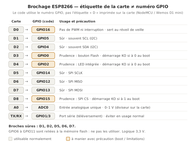
On a NodeMCU or a D1 mini, the silkscreen marks the pins D0, D1, D2…, and those do not match the GPIO numbers. For example D1 = GPIO5, D2 = GPIO4, D5 = GPIO14. The safest route is to use the Dxx constants (already defined by the core) rather than the raw numbers:
const int RELAIS = D1; // = GPIO5, but you reason with the board label
The boot pins
GPIO0, GPIO2 and GPIO15 decide the mode at reset (normal execution or flashing). Wiring them as outputs in a way that forces a wrong state at start-up stops the chip from booting. In practice: avoid putting a load on them that pulls them to the wrong level, and prefer other pins for your free outputs. GPIO16 is a special case (no interrupt, and it serves the deep sleep wake-up when wired to RST).
A single ADC
The ESP8266 has only one analog input (A0), 10 bits wide. On the chip itself it reads 0–1 V. The NodeMCU and D1 mini boards add a divider so that the pin reads 0–3.3 V. Worth checking on your own board before wiring an analog sensor.
The Wi-Fi stack runs in the background
Wi-Fi is handled in the background by the chip. If loop() runs a long computation without handing back control, the watchdog ends up restarting the board. The rule: keep the loop short, and insert yield() (or a delay()) in any extended wait. That is the price of built-in Wi-Fi. The stack has to be allowed to breathe.
Example — Connecting to Wi-Fi
This sketch connects the board to a Wi-Fi network and prints its IP address. It shows the door in use (Arduino + ESP8266WiFi) and the good habit of a delay() that lets the stack run.
#include <ESP8266WiFi.h> // the ESP8266 Wi-Fi stackconst char* ssid = "MonReseau"; // name of the network to joinconst char* motdepasse = "MonMotDePasse"; // its WPA keyvoid setup() { Serial.begin(115200); // open the serial monitor to follow the connection WiFi.begin(ssid, motdepasse); // start connecting (it is not instant) Serial.print("Connecting"); while (WiFi.status() != WL_CONNECTED) { // as long as the link is not up delay(500); // delay() hands back to the Wi-Fi stack (avoids the watchdog) Serial.print("."); // one dot per attempt, to see it progressing } Serial.println(); Serial.print("Connected. IP: "); Serial.println(WiFi.localIP()); // the address handed out by the router}void loop() { // short loop: let the Wi-Fi stack breathe}
In the serial monitor you watch the connection progress, then the IP address handed to the board. From there, the code is identical to an ESP32 one: the ESP8266WiFi API mirrors the ESP32 one. For the concepts (station versus access-point mode, reconnection, client and server), see Wi-Fi on the ESP32.
The monitor output tells the story of the connection:
Connecting.....
Connected. IP: 192.168.X.X
Each dot is one turn of the waiting loop, so half a second: their number measures how long joining the network took. The address itself is handed out by the router. Yours will be different, and it is the one you will type into a browser to reach the board.
Pitfalls
Confusing Dxx and GPIO. D1 is not GPIO1. Use the Dxx constants, or know your board’s offset.
Blocking a boot pin. GPIO0/2/15 as an output at the wrong level at reset → no start-up. Keep other pins for your free outputs.
Misjudging the ADC. A single input A0, 0–1 V on the chip (0–3.3 V on the board through a divider), 10 bits. Check the board.
Starving the Wi-Fi stack. A long computation with no yield()/delay() trips the watchdog and restarts the board. Keep loop() short.
Applying 5 V. The ESP8266 is not 5 V tolerant: shift the level of incoming signals.
Expecting Bluetooth. The ESP8266 has no Bluetooth. If the project needs it, the answer is the ESP32.
Exercises
Exercise 1 — The right pin
Blink an external LED wired to D6. Which GPIO is that really, and why is D6 a better thing to write than the number?
The wiring is the one from getting started — a series resistor then the LED anode, cathode to GND — on D6 instead of D5.
Solution
const int LED = D6; // D6 = GPIO12 on a NodeMCUvoid setup() { pinMode(LED, OUTPUT); }void loop() { digitalWrite(LED, HIGH); delay(500); digitalWrite(LED, LOW); delay(500);}
D6 = GPIO12. Writing D6 (the core’s constant) rather than 12 avoids the classic “D6 = GPIO6” mistake: the board labels and the GPIO numbers do not line up.
Exercise 2 — Connection and signal quality
Connect the board to Wi-Fi, then print the IP address and the received signal strength (RSSI, in dBm). Hint: WiFi.RSSI().
The RSSI (typically between −30 dBm right next to the router and −90 dBm at the edge of range) gives an idea of the link quality, useful for diagnosing dropouts. The API is the same as on the ESP32.
Special case — beyond the first Wi-Fi
HTTP server or client, MQTT — the ESP8266 hosts a small web server or publishes over MQTT just as the ESP32 does. The libraries and the method are shared (see Wi-Fi on the ESP32).
Deep sleep — ESP.deepSleep(µs) puts the chip into deep sleep. Waking up goes through a reset, which means GPIO16 has to be wired to RST. The principle is close to the deep sleep of the ESP32.
Where it fits in the project
Step 4 of the proof of concept phase — the ESP8266 Arduino core is the environment of the PoC of a Wi-Fi connected object built on a board you already have: you validate the network connection and the sensor reading early, keeping the pin constraints in mind.
Choosing the target — if the PoC turns up a need for Bluetooth, for more pins or for more power, that is the signal to move to the ESP32. The Wi-Fi code carries over almost as it stands.
Knowing the four quirks (labels, boot pins, single ADC, a Wi-Fi stack to spare) is enough to work with the ESP8266 calmly: the rest is Arduino, and the Wi-Fi is the ESP32 one.