Getting started with the ESP8266 means installing ESP8266 board support in the Arduino IDE, recognising the board (a NodeMCU in this example), and uploading a first program. Since the ESP8266 is programmed inside the Arduino framework, most of the moves are already familiar. One step is added (installing the ESP8266 core), and a small trap waits at the first blink: the on-board LED is active low. The target program is still the Blink, the embedded equivalent of “Hello World”.
What is it for?
Getting started validates the whole chain in one go: editor, compiler, ESP8266 support, USB-to-serial, upload, link. If one link is broken, the Blink does not blink, and you know it straight away, on trivial code.
Beyond the first program, this step is where you anchor the moves (selecting the board, the port, the speed, uploading, the serial monitor) and where you meet the quirks of the ESP8266 from the outset: the USB-to-serial driver to install, the active-low LED, the 3.3 V reflex.
Step by step
Five steps: install the Arduino IDE, add ESP8266 support, install the USB-to-serial driver, select the board, load the Blink.
1. Install the Arduino IDE
Download the Arduino IDE 2.x from arduino.cc (Software section). ESP8266 support is added to it through the boards manager (step 2).
2. Add ESP8266 support
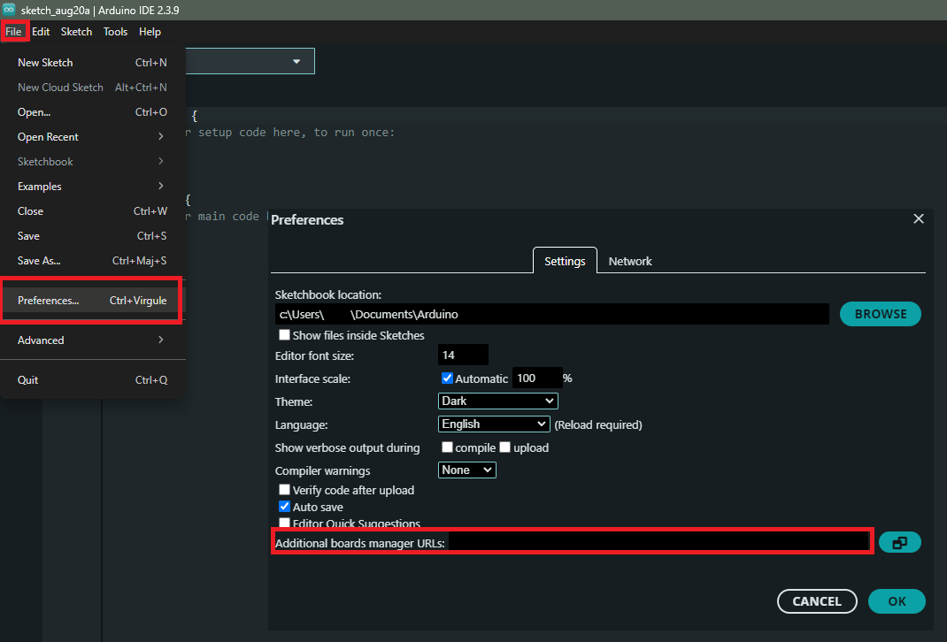
Open Fichier → Préférences (File → Preferences), and in URL de gestionnaire de cartes supplémentaires (Additional boards manager URLs), add:
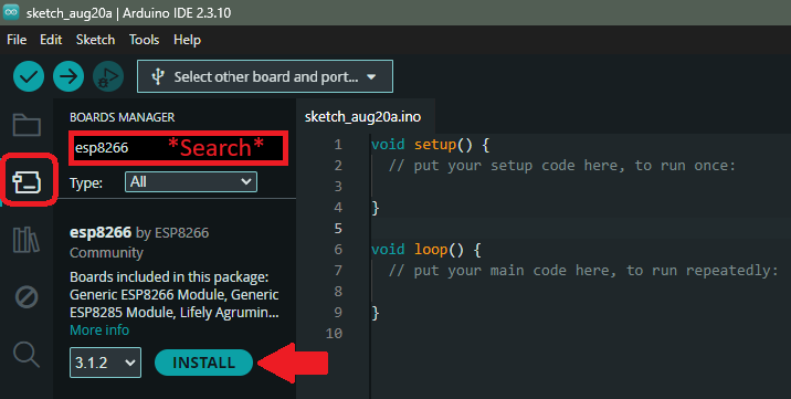
Open the gestionnaire de cartes (Boards Manager), search for esp8266, and install the “esp8266” by ESP8266 Community package. Take the latest 3.x version offered in the drop-down, which is the current stable branch of the core. The tutorials of this module refer to it.
3. Install the USB-to-serial driver
Unlike many recent boards, the NodeMCU and D1 mini use a USB-to-serial chip (often a CH340, sometimes a CP2102) that needs a driver on Windows if the board is not recognised. Install the driver matching your board, then plug it back in.
4. Plug the board in and select board and port
Plug the board in with a USB data cable. Two routes then lead to the selection, depending on whether the IDE recognises your board or not.
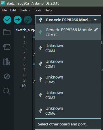
Common case — the toolbar selector. Pull down the selector at the top of the window: the board that was detected appears there with its port.
On a NodeMCU, whose USB-to-serial bridge is a third-party chip, the board shows as Unknown until it has been paired at least once, and that is normal (see Pitfalls). Go through Select other board and port…, pick the board on the left and your port on the right: the pairing is remembered.
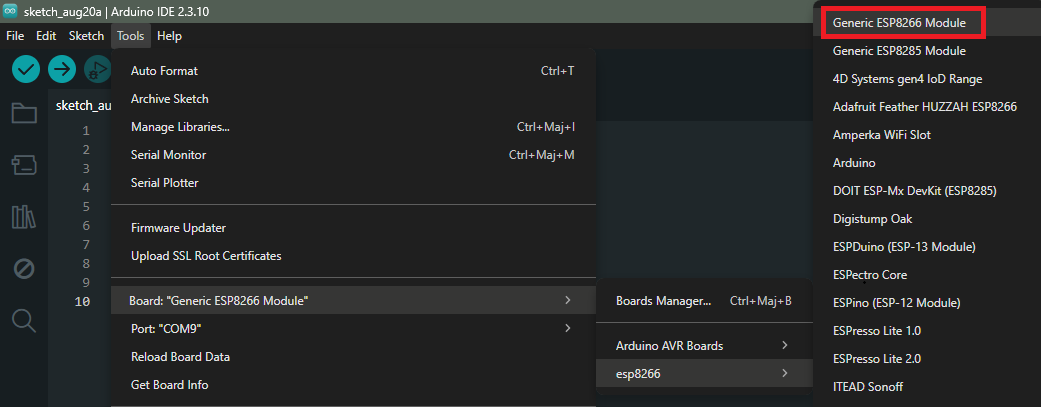
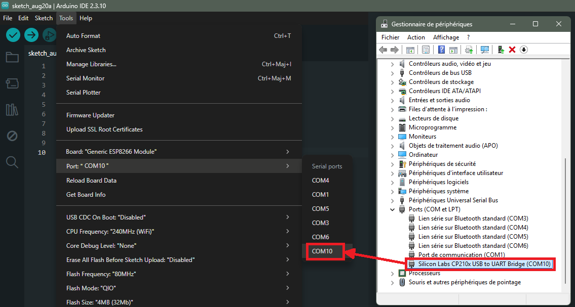
Manual route — the Outils menus. It works in every case. Outils → Type de carte → esp8266 (Tools → Board → esp8266), then “Generic ESP8266 Module”: this definition suits any ESP8266 board and it is the one used by the screenshots on this page. If yours has its own entry in the list (NodeMCU 1.0 (ESP-12E Module), LOLIN(WEMOS) D1 mini…), you can pick it: it presets the flash size and adds the D0–D8 silkscreen labels, at the price of code that no longer carries over as it stands from one board to another.
Then Outils → Port (Tools → Port), leaving the upload speed at its default: COMx on Windows, /dev/ttyUSB0 on Linux, /dev/cu.usbserial-... on macOS.
What remains is knowing which of those ports is yours. On Windows, the Device Manager names it explicitly: under Ports (COM et LPT) (Ports (COM & LPT)), the board appears under the name of its interface chip, here Silicon Labs CP210x USB to UART Bridge (COM10). The other entries are most often Bluetooth serial links with nothing to do with the board: they are the ones filling the port selector with “Unknown”.
5. Load the Blink — mind the active-low LED
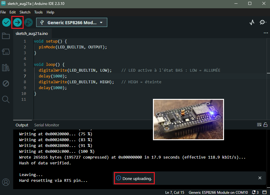
Type in this sketch. ESP8266 quirk: the on-board LED is active low. It lights at LOW and goes out at HIGH, the opposite of the Arduino reflex:
Click Téléverser (Upload, the arrow icon). On a NodeMCU or a D1 mini, the auto-reset (DTR/RTS lines) puts the board into programming mode with no button press. The console shows the progress, then the board restarts and the LED blinks.
Tip
If the LED looks “inverted”. That is normal and expected: on the ESP8266, LOW lights it. If you meant to switch it off, write HIGH. Plenty of beginners take this for a bug. It is just the inverted logic of the on-board LED.
Example — Blink modified
Change the timings to check that you are in control of the behaviour:
Upload again: a short flash once a second. This small step — change, upload, observe — is the basic move of every tutorial that follows.
Pitfalls
ESP8266 support not installed. Without step 2, no ESP8266 board under Outils → Type de carte (Tools → Board). The most frequent oversight.
D0–D8 labels unknown to the compiler. They are silkscreened on the board, but they are only defined by the board-specific definitions in the manager (NodeMCU 1.0, D1 mini…). Under “Generic ESP8266 Module”, const int LED = D5; fails to compile with 'D5' was not declared in this scope. Write the GPIO number (14 for the pin silkscreened D5), which works in every case.
USB-to-serial driver missing. Board not detected (no port): install the matching CH340 or CP2102 driver (step 3).
Port marked Unknown. On a board with a third-party USB-to-serial bridge — CH340 as well as CP2102 — the IDE shows Unknown next to the port: the bridge announces its own USB identifier, not that of a board, so the IDE has nothing to attach the port to. This is not a driver fault. Windows does show the chip under Ports (COM et LPT) (Ports (COM & LPT)), for example Silicon Labs CP210x USB to UART Bridge (COMx). Pair the board with the port once through Select other board and port…: the pairing is remembered.
LED “the wrong way round”. The on-board LED is active low: LOW = lit. It is not a bug.
“Charge-only” cable. Board powered but no port: change to a data cable.
The 5 V reflex from Arduino. The ESP8266 runs 3.3 V and is not 5 V tolerant: do not apply 5 V to a pin (see logic levels).
Exercises
Exercise 1 — Off, then blinking
Write a program that leaves the LED off for 3 seconds, then blinks it 5 times quickly (100 ms lit / 100 ms out), before starting over. Mind the inverted logic.
Solution
void setup() { pinMode(LED_BUILTIN, OUTPUT);}void loop() { digitalWrite(LED_BUILTIN, HIGH); // out delay(3000); for (int i = 0; i < 5; i++) { digitalWrite(LED_BUILTIN, LOW); // lit delay(100); digitalWrite(LED_BUILTIN, HIGH); // out delay(100); }}
The trap is the inverted logic: HIGH switches off, LOW lights. The for loop factors out the five flashes.
Exercise 2 — External LED
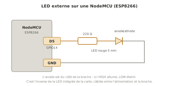
Wire an external LED (with its ~220 Ω resistor) to the pin silkscreened D5, that is GPIO 14, and blink it the “normal” way (HIGH = lit). Why is the logic not inverted this time?
Solution
const int LED = 14; // GPIO14, silkscreened "D5" on the boardvoid setup() { pinMode(LED, OUTPUT);}void loop() { digitalWrite(LED, HIGH); // anode to the pin: HIGH = lit delay(500); digitalWrite(LED, LOW); delay(500);}
The inverted logic only concerned the on-board LED, which is wired between the supply and the pin. An external LED wired anode to pin lights normally at HIGH. The pin is named by its GPIO number rather than by the D5 label: that label only exists under the board-specific definitions (see Pitfalls), whereas 14 compiles everywhere. This gap between silkscreen and numbering is set out in programming with the Arduino core.
Special case — ESP-01, NodeMCU Lua, PlatformIO
ESP-01 — no USB and no auto-reset: you need a USB-to-serial adapter and you have to force programming mode (GPIO0 to ground during reset) before uploading.
NodeMCU (Lua) / MicroPython — other firmwares exist for the ESP8266. This wiki sticks to the Arduino core.
PlatformIO — handles the ESP8266 with versioning and multiple files, handy as soon as the project grows.
Where it fits in the project
Step 4 of the proof of concept phase — the first compilation and the first upload onto the target are the founding act of the software PoC. As long as the Blink does not blink, nothing downstream is credible.
Every ESP8266 tutorial downstream — do the Blink at least once, on the target hardware, as early as possible.