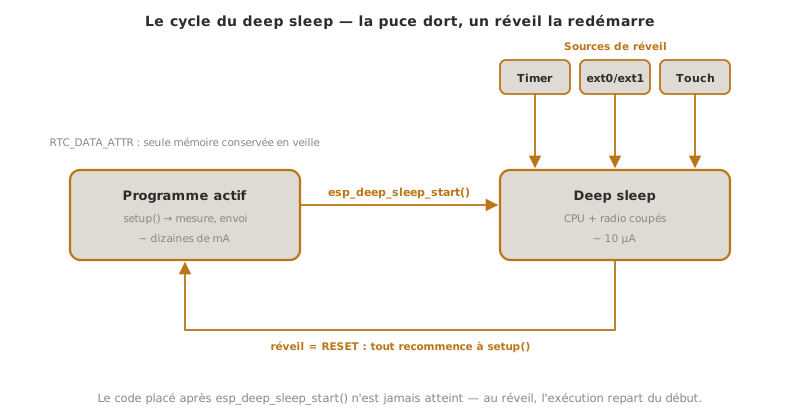
Deep sleep is the very low power mode of the ESP32: the processor and the radio are switched off, consumption drops from around ten milliamps to around ten microamps, and the chip only wakes on a chosen event (a delay, a button, a touch). This is what makes the ESP32 viable on battery: a sensor that wakes, measures, transmits and goes back to sleep spends most of its life consuming almost nothing. Power management in general is covered in deep sleep. This page gives the ESP32 incarnation of it.
What is it for?
Deep sleep answers one precise need: running for a long time on a small battery when the system has nothing to do most of the time.
Extending battery life by a huge factor. A station measuring every 10 minutes can sleep 99.9% of the time. The gain is not on the active consumption but on the idle one: going from 20 mA to 10 µA at rest takes a coin cell from a few days to several months.
Waking at the right moment. The wake-up is triggered by a timer (periodic measurement), a button or sensor (event), or a touch (interaction), and the chip sleeps until then.
Warning
Waking up is a RESET, not a resumption. On wake-up the ESP32 restarts: setup() is replayed from the beginning, code placed afteresp_deep_sleep_start() is never reached, and every ordinary variable is reinitialised. Only the RTC memory (see below) survives. This is misconception number one about deep sleep.
Waking on a timer (the most common case)
Two lines: arm the timer, enter sleep. The delay is in microseconds.
#define uS_PER_S 1000000ULL // microseconds per secondvoid setup() { Serial.begin(115200); delay(100); // gives USB time to come up Serial.println("Awake! Working..."); // ... measure, transmit ... esp_sleep_enable_timer_wakeup(10 * uS_PER_S); // sleep for 10 s Serial.println("Going to sleep."); Serial.flush(); // empty the port before cutting power esp_deep_sleep_start(); // past this point, nothing runs}void loop() {} // never reached in deep sleep
All the work happens inside setup(): on each wake-up the board runs setup(), does its job, and goes back to sleep. loop() stays empty. Here #define is legitimate (a scale constant used in a duration calculation). For pins or thresholds, prefer const.
RTC memory: what survives sleep
To keep a piece of information from one wake-up to the next (a counter, a state), you put it in RTC memory, which stays powered during sleep, with the RTC_DATA_ATTR attribute:
RTC_DATA_ATTR int wakeCount = 0; // survives deep sleepvoid setup() { Serial.begin(115200); delay(100); wakeCount++; // incremented on each wake-up Serial.print("Wake-up no. "); Serial.println(wakeCount); esp_sleep_enable_timer_wakeup(5 * 1000000ULL); esp_deep_sleep_start();}void loop() {}
Without RTC_DATA_ATTR, wakeCount would start again from zero on each wake-up (since it is a RESET). With it, it accumulates.
Example — A periodic measuring station
The typical pattern for a battery-powered sensor: wake every 30 seconds, read an analogue sensor, print, keep a cycle counter, then go back to sleep.
#define uS_PER_S 1000000ULLconst int SENSOR = 34; // ADC1const uint64_t PERIOD_S = 30; // interval between two measurementsRTC_DATA_ATTR int cycle = 0; // kept between wake-upsvoid setup() { Serial.begin(115200); delay(100); cycle++; int reading = analogRead(SENSOR); Serial.print("Cycle "); Serial.print(cycle); Serial.print(" — reading = "); Serial.println(reading); // ... here: send the reading (Wi-Fi/BLE) before sleeping ... esp_sleep_enable_timer_wakeup(PERIOD_S * uS_PER_S); Serial.flush(); esp_deep_sleep_start();}void loop() {}
On the serial monitor you see one line appear every 30 seconds, with the cycle number going up. In between, the board is in deep sleep: on a bare module (without the development board), consumption there is of the order of a microamp.
Since each wake-up is a restart, each line is preceded by the chip’s boot log, omitted here:
The number does not start again from 1: that is the whole demonstration of RTC_DATA_ATTR. Without it, the four lines would all read Cycle 1.
Waking on an external event
Instead of (or in addition to) the timer, the ESP32 can wake on a pin:
esp_sleep_enable_ext0_wakeup(GPIO_NUM_33, level) — wake on one pin (a button), at level 0 (LOW) or 1 (HIGH).
esp_sleep_enable_ext1_wakeup(mask, mode) — wake on several pins at once.
These wake-ups only accept the RTC pins (GPIO0, 2, 4, 12-15, 25-27, 32-39). An ordinary pin does not wake the chip. After the wake-up, esp_sleep_get_wakeup_cause() tells you why the board woke (timer, ext0, touch…), so you can react differently depending on the source.
Pitfalls
Believing the code resumes where it stopped. Waking up is a RESET: setup() replayed, loop() never reached before sleep, variables back to zero. All the work goes into setup(), before esp_deep_sleep_start().
A variable lost between two wake-ups. A counter or a state declared normally starts again from zero on each wake-up. Declare it RTC_DATA_ATTR so that it survives.
A non-RTC pin for an external wake-up.ext0/ext1 only accept RTC pins. An ordinary pin is ignored, and the board never wakes.
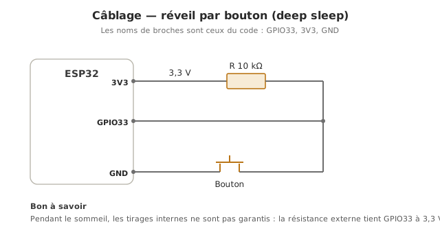
A floating button during sleep. During deep sleep the internal pull resistors are not guaranteed. A wake-up button needs an external resistor (or the RTC pull to be enabled explicitly), otherwise noise causes spurious wake-ups.
Serial cut off too early. Without Serial.flush() before esp_deep_sleep_start(), the last messages may never leave. And a delay(100) at the start of setup() gives USB time to come back up before printing.
Disappointing consumption on a development board. The dev board (DevKit) keeps its USB-serial chip, its power LED and its regulator powered. It consumes far more than the microamp figure quoted. Very low consumption is measured on the bare module, not on the dev kit.
Exercises
Exercise 1 — Button wake-up and wake-up cause
Set up a timer wake-up (every 20 s) and a button wake-up on GPIO33. On each wake-up, print why the board woke (timer or button).
Answer to exercise 1
You arm both sources, then query the cause on wake-up.
#define uS_PER_S 1000000ULLvoid setup() { Serial.begin(115200); delay(100); // why did we wake up? esp_sleep_wakeup_cause_t cause = esp_sleep_get_wakeup_cause(); switch (cause) { case ESP_SLEEP_WAKEUP_TIMER: Serial.println("Wake-up: timer"); break; case ESP_SLEEP_WAKEUP_EXT0: Serial.println("Wake-up: button"); break; default: Serial.println("Initial start-up"); break; } // arm both sources for the next sleep esp_sleep_enable_timer_wakeup(20 * uS_PER_S); esp_sleep_enable_ext0_wakeup(GPIO_NUM_33, 0); // button to GND, LOW level Serial.flush(); esp_deep_sleep_start();}void loop() {}
The switch on the cause lets you act differently: a routine measurement on a timer wake-up, an immediate action on a button wake-up. The button on GPIO33 (an RTC pin) goes to ground, with an external pull-up resistor to 3.3 V.
Exercise 2 — Estimating battery life
A board (bare module) draws 80 mA for 2 s of activity (wake-up, measurement, Wi-Fi transmission), then 10 µA in deep sleep, with one cycle every 10 minutes. Estimate the average consumption. What order of magnitude of battery life on a 1000 mAh cell?
Cycle = 600 s; active = 2 s at 80 mA; sleep = 598 s at 0.01 mA.
Active charge: 80 mA × 2 s = 160 mA·s. Sleep charge: 0.01 mA × 598 s ≈ 6 mA·s.
Average current ≈ (160 + 6) / 600 ≈ 0.28 mA.
Battery life ≈ 1000 mAh / 0.28 mA ≈ 3500 h ≈ 5 months.
Sleep weighs almost nothing (6 against 160): what makes the battery life is the shortness and rarity of the activity, not only the standby current. Without deep sleep (80 mA continuously), the same cell would last about 12 h.
Special case — Light sleep
Between normal operation and deep sleep sits light sleep: the chip suspends the processor but keeps its state (RAM, peripherals), and resumes execution where it stopped when it wakes, with no RESET. Consumption is in between (a few hundred µA to a few mA). You choose it when you want to save power without losing the context (with a low wake-up latency), where deep sleep forces you to rebuild everything on each cycle.
Where it fits in the project
Step 4 of the proof-of-concept phase. If the project runs on battery, validating a wake, measure, sleep cycle early and measuring the real consumption lifts the battery-life uncertainty, which is often a sizing constraint for a connected object.
Sizing the power supply. The estimate of average consumption (see exercise 2) drives the choice of battery and belongs in the technical design file.
Thinking the system around the sleep and wake cycle from the design stage onwards (what to do on wake-up, what has to survive) avoids discovering too late that an “always on” architecture rules out the battery life you were aiming for.
Going further
Deep sleep — the idea of saving energy by going to sleep (cross-cutting).
Wi-Fi · Bluetooth LE — wake, exchange, go back to sleep: the pattern of battery-powered connected objects.
ULP (Ultra Low Power coprocessor) — a tiny core that can watch a sensor while the main processor sleeps, and only wake it at the useful threshold.